
Brightness enhancement of diode light sources

a light source and diode technology, applied in the field of semiconductor laser diodes, can solve problems such as increasing the cost of the system

Inactive Publication Date: 2005-04-14
NORTHROP GRUMAN CORP
View PDF22 Cites 30 Cited by
  • Summary
  • Abstract
  • Description
  • Claims
  • Application Information

AI Technical Summary

Benefits of technology

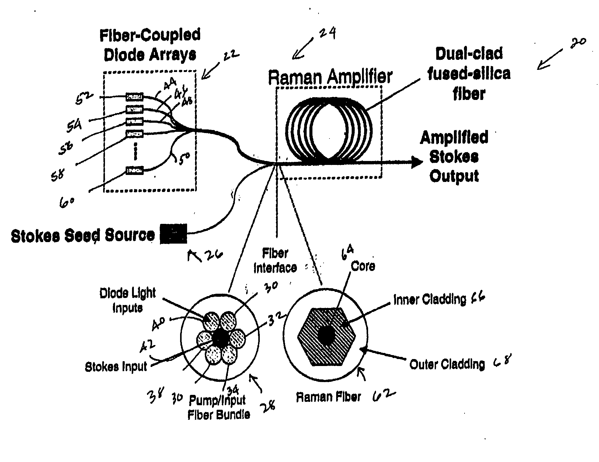
[0011] The present invention relates to a system for combining the output light beams of a plurality of semiconductor laser diodes, for example, to form a combined light beam with increased brightness. The output light beams from the semiconductor laser diodes are coupled to a plurality of optical fibers forming a fiber coupled diode array. The optical fibers forming the fiber coupled diode array are coupled to a dual clad optical fiber with a central core, an inner cladding and an outer cladding. The output light beams from the optical fibers from the fiber coupled diode array are coupled to the inner cladding of a dual clad optical fiber as pump light. A Stokes seed source is applied to the central core and is amplified by the pump light by stimulated Raman scattering. The configuration in accordance with the present invention provides a output Stokes light beam from the central core with a relatively higher brightness level than known techniques which merely combine the output light beams from a plurality of semiconductor diodes and eliminates the need for a relatively precise alignment and the cost associated with the lenses required by known systems.

Problems solved by technology

In addition, such prior art systems require a number of lenses which increase the cost of the system.

Method used


Image

  • Brightness enhancement of diode light sources
  • Brightness enhancement of diode light sources

Examples


Embodiment Construction

[0014] The present invention relates to a technique for providing enhanced brightness of one or more semiconductor diode lasers. Unlike known systems, the system in accordance with the present invention eliminates the need for precise alignment and multiple lenses while at the same time provides enhanced brightness of a semiconductor diode output beam. As will be discussed in more detail below, the system in accordance with the present invention combines the output light beams from a plurality of semiconductor diodes forming a diode array into a combined light beam in a dual clad optical fiber with a central core. A Stokes seed source is confined to the inner core of the optical fiber while the output light beams from a fiber coupled diode array are confined to an inner cladding. The fiber-coupled light beams act as a pump source to amplify the Stokes seed beam in the central core by way of stimulated Raman scattering to provide an output Stokes beam that is shifted in frequency and...


PUM


Abstract

Briefly, the present invention relates to a system for combining the output light beams of a plurality of semiconductor laser diodes, for example, to form a combined light beam with increased brightness. The output light beams from the semiconductor laser diodes are coupled to a plurality of optical fibers forming a fiber coupled diode array. The optical fibers forming the fiber coupled diode array are coupled to a dual clad optical fiber with a central core. The output light beams from the optical fibers from the fiber coupled diode array are coupled to the inner cladding of a dual clad optical fiber. A Stokes seed source is applied to the central core, and the inner-clad diode light acts as a pump source to amplify the Stokes beam by stimulated Ramans scattering, thereby transferring power from the inner cladding into Stokes beam in the central core. The configuration in accordance with the present invention provides a Stokes output light beam with a relatively higher brightness level than known techniques which merely combine the output light beams from a plurality of semiconductor diodes and eliminates the need for a relatively precise alignment and the cost associated with the lenses required by known systems.

Description

BACKGROUND OF THE INVENTION [0001] 1. Field of the Invention [0002] The present invention relates to semiconductor diode lasers and more particularly to brightness enhancement of semiconductor laser diodes utilizing stimulated Raman scattering. [0003] 2. Description of the Prior Art [0004] Semiconductor laser diodes are known in the art. Such semiconductor laser diodes are used in various applications including optical pumping of solid state lasers. Examples of such semiconductor diode lasers used in such applications are disclosed in commonly owned U.S. Pat. Nos. 5,555,254; 5,646,773; 6,094,297; and 6,178,040. Such semiconductor laser diodes are used to optically excite the Nd:YAG slabs to a relatively high energy meta-stable state. [0005] Techniques are known for increasing the output power and brightness or intensity of such semiconductor laser diodes. For example, U.S. Pat. No. 5,764,675 discloses a semiconductor diode laser array that optimizes the laser output power by optimiz...

Claims


Application Information

Patent Timeline
Patent Type & Authority Applications(United States)
IPC IPC(8): G02B6/02G02B6/036H01LH01S3/00H01S3/067H01S3/094H01S3/0941H01S3/30
CPCG02B6/02042G02B6/03622H01S3/06729H01S3/302H01S3/094003H01S3/094053H01S3/0941H01S3/06754
Inventor KOMINE, HIROSHI
Owner NORTHROP GRUMAN CORP
Learn More