Material stirring device of unloading trough

A technology of stirring spindle and storage tank, which is applied to mixers, mixer accessories, mixers and other directions with rotating stirring devices, can solve the problems of uneven force on the combined oil seal, inability to guarantee the sealing effect, and poor oil seal sealing effect, etc. To achieve the effect of reducing maintenance costs, strong scalability, and good sealing effect

Active Publication Date: 2013-04-17
广西蓝星大华化工有限责任公司
View PDF4 Cites 6 Cited by
  • Summary
  • Abstract
  • Description
  • Claims
  • Application Information

AI Technical Summary

Problems solved by technology

The front-end sealing structure 104 and the rear-end sealing structure 108 adopted by this existing device are as attached figure 2 As shown, it is composed of the first gland 201, the second gland 202, the sealing seat 203 and the combined oil seal 205. The sealing seat 203 is installed at both ends of the stirring shaft and connected with the flanges 204 at both ends of the storage tank with bolts. , and then put the combination oil seal 205 into the seal seat 203, press the gland 201 and the gland 202 into the two ends of the seal seat 203 at the same time and fasten them with bolts to ensure the correct positioning of the combination oil seal in the seal seat, as shown in the attached figure 2 As shown, the use of this sealing structure makes the combined oil seal inside the front and rear end seals seal the material brought out during the rotation of the stirring shaft during the rotation of the stirring shaft, but the sealing effect of the shaft end sealing structure itself on the oil seal It is poor, it is only sealed by two glands, and a good sealing effect cannot be guaranteed during the rotation of the stirring shaft, and because the span of the entire stirring shaft in the unloading tank is large (5750mm), the load on the bearing is large, and the stirring rotation During the process, due to the weight of the shaft itself and the weight of the material, the stirring shaft is bent and deformed due to the large span. The combined oil seal in the middle is unevenly stressed, the local friction force is increased, and the combined oil seal is prone to wear, resulting in a larger radial gap between the combined oil seal and the stirring shaft, which eventually causes the material to leak from both ends of the stirring shaft, reducing the yield of the product. At the same time, due to the limitation of the site, it is difficult to recycle the leaked material, and finally it can only be discharged into the waste water tank, which has caused a lot of processing pressure for environmental protection. Therefore, the front and rear ends of the stirring shaft in the material stirring device of the unloading tank in the prior art are sealed The sealing effect of the structure is poor, resulting in serious leakage of materials during the mixing process

Method used


Image

  • Material stirring device of unloading trough
  • Material stirring device of unloading trough
  • Material stirring device of unloading trough

Examples


Embodiment Construction

[0029] The technical solution of the present invention will be described in detail below in conjunction with the accompanying drawings, but the present invention is not limited thereto.

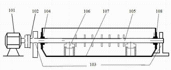
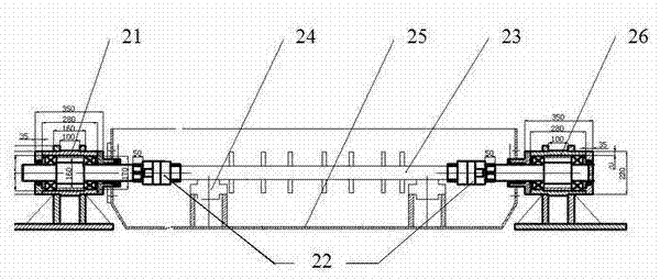
[0030] as attached image 3 As shown, the material stirring device of the unloading tank according to the present invention includes a front-end sealing structure 21, an Oldham coupling 22, a supporting roller 24, a material storage tank 25, a stirring spindle 23 and a rear-end sealing structure 26. The front end sealing structure 21 is installed on the front end of the material storage tank 25. One end of the front main shaft in the front end sealing structure 21 is connected to the reducer that provides power through a coupling, and the other end of the main shaft is connected to the Oldham coupling 22. The other end of the block coupling 22 is connected to one end of the stirring main shaft 23, and the other end of the stirring main shaft 23 is connected to another Oldham coupling 22, whic...


PUM


Abstract

The invention provides a shaft-end sealing structure, and provides a material stirring device of an unloading trough based on the shaft-end sealing structure, which can effectively protecting a stirred material from leakage. The shaft-end sealing structure comprises a main shaft, two bearings, a bearing base, a gland of the bearing base, a sealing base, a gland of the sealing base and sealing rings, wherein the two bearings are installed on the main shaft distantly and are arranged inside the bearing base; one end of the bearing base is connected with the gland of the bearing base; the other end of the bearing base is connected with the sealing base; the sealing rings are arranged between the gland of the bearing base and the sealing base and between the gland of the bearing base and the main shaft respectively; and a stirring shaft of the material stirring device of the unloading trough is divided into three sections, namely a front-end main shaft in a front-end sealing structure, a stirring main shaft in the trough and a back-end main shaft in a back-end sealing structure. Through the sealing structure, the sealing effect is greatly improved; and the material stirring device of the unloading trough can completely avoid material leakage, so that the service life is prolonged, the product yield is increased and the environmental burden is relieved.

Description

technical field [0001] The invention relates to the field of shaft sealing, and more specifically relates to a sealing structure of a material stirring shaft of a chip unloading tank and a material stirring device of a chip unloading tank developed based on the sealing structure. Background technique [0002] In the prior art, the material stirring device of the unloading tank in the titanium dioxide industry is as attached figure 1 As shown, it includes a reducer 101, a coupling 102, a supporting bearing seat 103, a front sealing structure 104, a stirring shaft 105, a supporting roller 106, a storage tank 107 and a rear sealing structure 108, and the coupling is directly connected through the reducing machine 101. The mixer 102 drives the stirring shaft 105 to stir the material in the tank, and the stirred material is discharged through the discharge hole at the bottom of the tank, and the stirred material is transported to the storage tank in the next process through the f...

Claims


Application Information

Patent Timeline
Patent Type & Authority Applications(China)
IPC IPC(8): B01F7/04B01F15/00
Inventor 吴毅
Owner 广西蓝星大华化工有限责任公司
Why Eureka
Try Eureka