Three-roller multi-station adjusting forming equipment for producing radiating tubes

A technology for forming equipment and heat dissipation pipes, applied in heat exchange equipment and other directions, can solve the problems of waste of raw materials, increased production costs of enterprises, working efficiency of forming equipment, and low product yield of product accuracy, so as to save raw materials and improve the yield of finished products. , to achieve the effect of multi-directional adjustment

Inactive Publication Date: 2013-04-17
淮安市贝克铝热传输有限公司
View PDF6 Cites 0 Cited by
  • Summary
  • Abstract
  • Description
  • Claims
  • Application Information

AI Technical Summary

Problems solved by technology

[0004] The technical problem to be solved by the present invention is to provide a three-roll multi-position adjustable forming equipment for heat pipe production. The present invention not only effectively solves the problem of forming equipment used in the process of processing heat pipes in the industry at present, but cannot adjust each forming roll through online The distance between them leads to the problems of low working efficiency, product precision and product yield of molding equipment, and effectively solves the problem of traditional molding equipment, which requires continuous trial production, adjustment, trial production, and adjustment process. The waste of raw materials is serious, resulting in Increase in production costs of enterprises

Method used


Image

  • Three-roller multi-station adjusting forming equipment for producing radiating tubes
  • Three-roller multi-station adjusting forming equipment for producing radiating tubes
  • Three-roller multi-station adjusting forming equipment for producing radiating tubes

Examples


Embodiment Construction

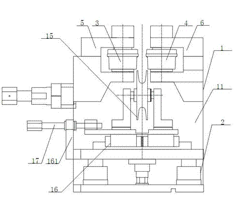
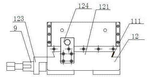
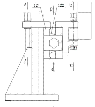
[0018] Such as figure 1 , 2 , 3, 4, 5, and 6, the present invention includes an upper roll forming device 1 and a lower roll forming device 2, and the upper roll forming device 1 includes a frame body 11 and a connecting slider 12, and the frame body 11 is vertically The dovetail groove A111 is provided in the direction, the dovetail guide rail A121 is arranged vertically on one side of the connecting slider 12, and the dovetail groove B122 is arranged horizontally on the opposite side, the dovetail groove A111 of the rack body 11 and the dovetail connecting slider 12 The guide rail A121 is matched and clamped, and the connecting slider 12 is provided with the left forming roller 3 and the right forming roller 4 through the dovetail groove B122. The connecting slider 12 is slidably connected, and the left forming roller 3 and the right forming roller 4 are respectively rotatably connected to the sliding base A5 and the sliding base B6. One end of the horizontal adjustment sc...


PUM


Abstract

The invention discloses three-roller multi-station adjusting forming equipment for producing radiating tubes. The three-roller multi-station adjusting forming equipment comprises an upper roller forming device and a lower roller forming device. The upper roller forming device comprises a framework body and a connecting slider, a dovetail groove A is arranged on the framework body in the vertical direction, a dovetail guide rail A is arranged on one side of the connecting slider in the vertical direction, a dovetail groove B is arranged on the opposite side of the connecting slider in the horizontal direction, the dovetail groove A of the framework body is fittingly clamped with the dovetail guide rail A of the connecting slider, the connecting slider is provided with a left forming roller and a right forming roller via the dovetail groove B, a sliding base A and a sliding base B are synchronously connected with a horizontal adjusting lead screw in a threaded opening and closing manner by right-handed and left-handed thread structures, and the horizontal adjusting lead screw is provided with a synchronous adjusting barrel. The three-roller multi-station adjusting forming equipment not only effectively solves problems of low work efficiency and yield of existing forming equipment due to the fact that distances among various forming rollers of the existing forming equipment cannot be adjusted in an online manner, but also effectively solves the problem of severe wastage of raw materials due to the fact that continuous trial-production is required by the traditional forming equipment.

Description

[0001] technical field [0002] The invention relates to the technical field of processing equipment for aluminum heat dissipation pipes, in particular to a three-roller multi-position adjustable forming equipment for heat dissipation pipe production. Background technique [0003] With the rapid development of China's automobile and air-conditioning industries, more and more high-frequency welded round aluminum tubes, manifolds, and intercooler tubes are applied to mid-to-high-end automotive air conditioners, household and industrial air conditioners, and heat pipes are formed The equipment is one of the necessary process equipment in the process of high-frequency welding flat aluminum tubes, manifolds, and intercooler tubes. At present, the heat pipe forming equipment commonly used in the industry usually uses the left forming roll, right forming roll, and lower forming roll. The forming rollers are fixed on the frame. However, according to the specific size requirements of...

Claims


Application Information

Patent Timeline
Patent Type & Authority Applications(China)
IPC IPC(8): B21D53/06
Inventor 许小平魏雪冬王换喜王国利郭萍
Owner 淮安市贝克铝热传输有限公司
Why Eureka
Try Eureka