Remote control device and control method for pure electric crawler tractor

A remote control device and tractor technology, applied in the field of agricultural machinery research, can solve problems such as energy loss, achieve the effects of reducing energy consumption, improving control accuracy, and ensuring consistency

Inactive Publication Date: 2016-12-07
JIANGSU UNIV
View PDF8 Cites 9 Cited by
  • Summary
  • Abstract
  • Description
  • Claims
  • Application Information

AI Technical Summary

Problems solved by technology

However, the brakes, suspension lifting devices and suspension hydraulic cylinders work intermittently. When these devices do not work, it will inevitably cause a large amount of energy loss, especially for pure electric crawler tractors that use batteries as the only power source. loss cannot be ignored

Method used


Image

  • Remote control device and control method for pure electric crawler tractor
  • Remote control device and control method for pure electric crawler tractor
  • Remote control device and control method for pure electric crawler tractor

Examples


Embodiment 1

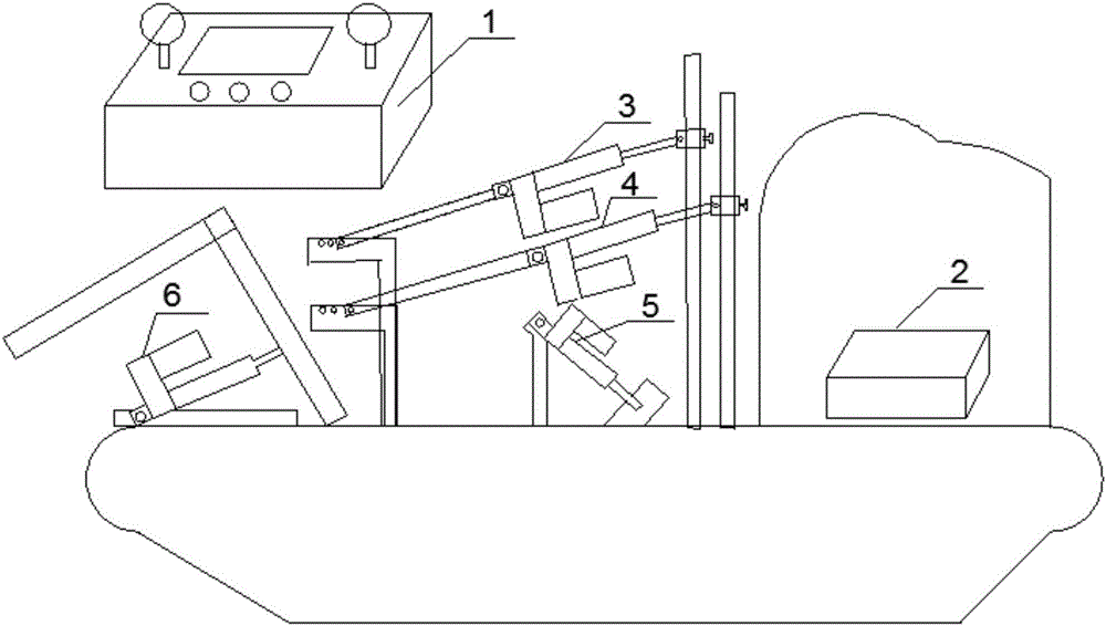
[0040] figure 1 Shown is an embodiment of the remote control device for pure electric crawler tractors according to the present invention. The remote control device for pure electric crawler tractors includes remote control 1, controller 2, left brake push rod 3, Right brake push rod 4, accelerator push rod 5 and suspension push rod 6. The remote controller 1 and the controller 2 carry out data transmission through the ZigBee wireless network; the left brake push rod 3 is installed between the left brake rod 302 and the left brake push rod bracket 303, and the left brake push rod The bracket 303 is fixed on the vehicle body floor; the right brake push rod 4 is installed between the right brake lever 402 and the right brake push rod bracket 403, and the right brake push rod bracket 403 is fixed on the vehicle body floor; The accelerator push rod 5 is installed between the accelerator push rod bracket 501 and the accelerator pedal 502, and the 501 is fixed on the vehicle body f...

Embodiment 2

[0057] like Figure 4 Shown is an implementation of using a smart phone to control a pure electric crawler tractor. The difference between the remote control device in the second embodiment and the first embodiment is that the remote control 1 is a smart phone, and the remote control 1 The wireless data transceiver module I105 is a built-in WiFi module of the mobile phone. The wireless data transceiver module I105 of the remote controller 1 and the wireless data transceiver module II201 of the controller 2 perform data transmission through the WiFi wireless network.

[0058] The remote controller 1 is a smart phone; the wireless data transceiver module I105 of the remote controller 1 is a built-in WiFi module of the mobile phone, and the wireless data transceiver module I105 and the wireless data transceiver module II201 perform data transmission through a WIFI wireless network. Device 1 also includes left and right steering slider 101-2, acceleration brake slider 102-2, touch...


PUM


Abstract

The invention relates to a remote control device and a control method for a pure electric crawler tractor belonging to the field of agricultural machinery. The remote control device comprises a remote controller, a controller, a left brake push rod, a right brake push rod, an accelerator push rod and a suspension push rod. The remote controller can send the control instruction to the controller and can receive the vehicle state parameter signal transmitted by the controller and display through a display screen; the controller and the vehicle CAN network are connected for receiving the complete vehicle state parameter signal transmitted by the vehicle controller and transferring to the remote controller as well as the control instruction transmitted from the remote controller to control the stretching and retracting of each push rod, therefore the tractor can be controlled to stop, advance, retreat, turn, and mount the farm tools. The remote control device adopts an electric push rod, which can keep the electric push rod to a fixed elongation length without the need of energy, by using the self-locking characteristic of the electric push rod. Compared with the prior patent and the product technology, the remote control device reduces the whole vehicle energy consumption significantly, while improving the control accuracy.

Description

technical field [0001] The invention belongs to the field of agricultural machinery research, and in particular relates to a remote control device and a control method for pure electric crawler tractors. Background technique [0002] At present, the brakes and suspension lifting devices of all remote control crawler tractors use hydraulic oil pumps as power sources. After the tractor is started, the hydraulic oil pumps are always running, so when the brakes and suspension lifting devices are not working, it will inevitably cause a lot of energy loss. Especially for pure electric crawler tractors that use batteries as the sole power source, the loss of the hydraulic oil pump cannot be ignored; in addition, the remote control that uses buttons has a large number of buttons, inflexible operations, and misoperation during driving. Possibility, and can only be used to control the stop, forward, backward, steering, and lifting of the farm implements of the tractor. It cannot obtai...

Claims


Application Information

Patent Timeline
Patent Type & Authority Applications(China)
IPC IPC(8): G08C17/02B62D55/00
CPCG08C17/02B62D55/00
Inventor 商高高张杰韩江义夏长高陈彪
Owner JIANGSU UNIV
Why Eureka
Try Eureka