Eureka AIR delivers breakthrough ideas for toughest innovation challenges, trusted by R&D personnel around the world.

Method for increasing recovery rate of converter gas

A converter gas, recovery technology, applied in the direction of manufacturing converters, etc., to achieve the effect of increasing recovery

Inactive Publication Date: 2013-04-17
QINHUANGDAO SHOUQIN METAL MATERIAL +1
View PDF2 Cites 4 Cited by
  • Summary
  • Abstract
  • Description
  • Claims
  • Application Information

AI Technical Summary

Problems solved by technology

Solve the problem of automatic and safe recovery of converter gas that meets the recovery conditions before the first slag removal (dephosphorization period) and after slag removal

Method used

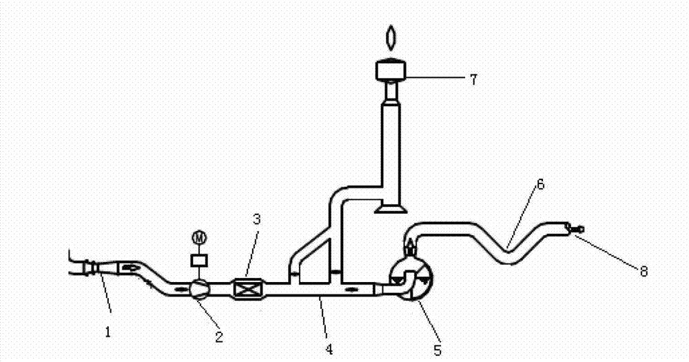
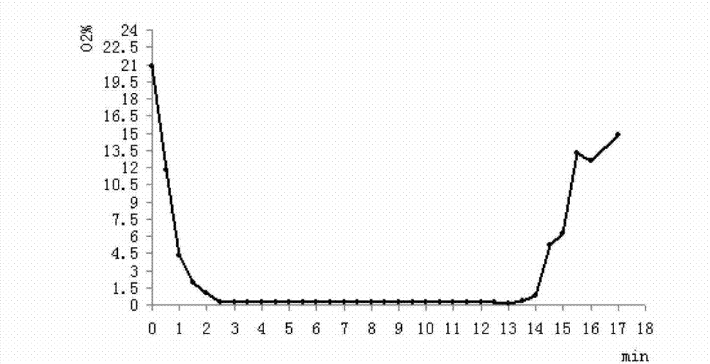
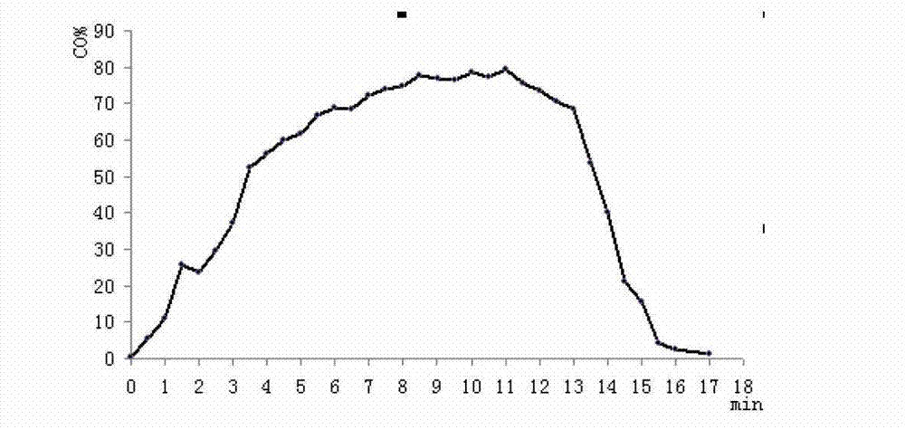

Image

  • Method for increasing recovery rate of converter gas
  • Method for increasing recovery rate of converter gas
  • Method for increasing recovery rate of converter gas

Examples


Embodiment 1

[0037] The furnace number is 2P05486:

[0038] 1. When the furnace steel is blown to 2′36″, the blowing of the oxygen lance is below the oxygen opening point, the skirt is at a low position, and there is no fault alarm for the three-way valve and the water reverse valve; the compressed air pressure is 0.493MPa; The through valve is closed; the fan speed is 1350r / min; the oxygen content is 0.08wt%; the CO content is 37.2wt%; the gas cabinet is 60100m 3 ;It takes 2.6 minutes to blow the lance, and the above conditions meet the conditions for the automatic gas recovery of the first lance lowering, and the gas recovery starts automatically.

[0039] 2. When the blowing reaches 4′35″, the oxygen lance blowing is below the oxygen opening point, the cover skirt is at a high position, and the three-way valve and water reverse valve have no fault alarm; the compressed air pressure is 0.460MPa; the bypass valve is at Closed state; fan speed 1350r / min; oxygen content 0.06wt%; CO content...

Embodiment 2

[0043] The furnace number is 1O07321:

[0044] 1. When the furnace steel is blown to 2′46″, the blowing of the oxygen lance is below the oxygen opening point, the cover skirt is at a low position, and there is no fault alarm for the three-way valve and the water reverse valve; the compressed air pressure is 0.466MPa; The through valve is closed; the fan speed is 1300r / min; the oxygen content is 0.04wt%; the CO content is 47wt%; the gas cabinet is 30900m 3 ; The blowing process lasted 2.77 minutes, and the above conditions met the conditions for automatic gas recovery in the first lowering of the lance, and gas recovery began automatically.

[0045] 2. When the blowing reaches 5'52", the blowing of the oxygen lance is below the oxygen opening point, the cover skirt is at a high position, and the three-way valve and water reverse valve have no fault alarm; the compressed air pressure is 0.459MPa; the bypass valve is at Closed state; fan speed 1300r / min; oxygen content 0.04wt%; ...


PUM


Abstract

The invention provides a method for increasing the recovery rate of a converter gas and belongs to the technical field of converter steelmaking. An oxygen gun is lowered below an oxygen opening point and the pressure of compressed air is 0.2-0.6 MPa; a bypass valve is closed; the rotation speed of a fan is 1000-1400 r / min; the content of oxygen is not more than 2 wt%; the content of CO is 30-100 wt%; the capacity of a gas holder is not more than 65,000 m<3>; and the gun is lowered to blow for 1.5-4 minutes; and if these conditions are all satisfied, the gas begins to be recycled. The capacity of the gas holder is 65,000-80,000 m<3>; the content of the oxygen is not less than 2 wt%; the content of CO is 20-30 wt%; alarming is given when a three-way valve fails to work or a check valve fails to work; the bypass valve is opened; the pressure of the compressed air is not more than 0.2 MPa; the rotation speed of the fan is 800-1,000 r / min; a housing is at a high level; and the gun is lifted above the oxygen opening point in the converter; and if these conditions are all satisfied, the gas is released. The method for increasing the recovery rate of the converter gas, provided by the invention, has the advantages that the average gas recycling time is prolonged by about 1-2 minutes and the gas recycling quantity per ton steel can be increased by about 10-20 %.

Description

technical field [0001] The invention belongs to the technical field of converter steelmaking, and in particular relates to a method for increasing recovery of converter gas. In particular, a method for increasing the recovery of converter gas when using the SGRP (converter slag-less steelmaking process technology) smelting process for steelmaking is described. Specifically, when converter steelmaking is smelted by SGRP technology, the converter gas that meets the recovery conditions before the first slag removal (dephosphorization period) and after slag removal is automatically recovered, thereby increasing the recovery of converter gas and reducing emissions. Rate. Background technique [0002] The main chemical reaction of oxygen top-blown converter steelmaking is: 2C+O 2 =2CO, so the furnace gas produced by converter blowing contains a large amount of CO. The size of the furnace gas volume and the CO content in the furnace gas mainly depend on the amount of oxygen suppl...

Claims


Application Information

Patent Timeline
Patent Type & Authority Applications(China)
IPC IPC(8): C21C5/30
Inventor 王永岗王占龙韩俊谭明祥王礁马文新杨发宋胜利王立新秦登平王洪宇孙硕猛朱志远王浩然杨建平
Owner QINHUANGDAO SHOUQIN METAL MATERIAL
Why Eureka
Eureka Blog
Learn More