Snow blower and pneumatic conveying system thereof

A technology of pneumatic conveying system and snow blower, which is applied in snow surface cleaning, construction, cleaning methods, etc., and can solve the problems of low snow blowing efficiency, poor fan flow conductivity, energy loss, etc.

Active Publication Date: 2013-04-17
ZOOMLION ENVIRONMENTAL IND CO LTD
View PDF7 Cites 6 Cited by
  • Summary
  • Abstract
  • Description
  • Claims
  • Application Information

AI Technical Summary

Problems solved by technology

Among them, the blades are of the same size and uniformly distributed along the circumferential direction, so that there are overlapping steady flow areas and vortex areas between adjacent blades. Since the steady flow areas are greatly affected by the vo

Method used


Image

  • Snow blower and pneumatic conveying system thereof
  • Snow blower and pneumatic conveying system thereof
  • Snow blower and pneumatic conveying system thereof

Examples


Embodiment Construction

[0060] Specific embodiments of the present invention will be described in detail below in conjunction with the accompanying drawings. It should be understood that the specific embodiments described here are only used to illustrate and explain the present invention, and are not intended to limit the present invention.

[0061] In the present invention, in the case of no contrary description, the used orientation words such as "up, down, left and right" usually refer to the up, down, left and right shown in the accompanying drawings; "inside and outside" Refers to the inside and outside of the outline of each part itself.

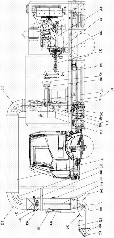
[0062] The present invention provides a snow blower, wherein the snow blower includes a fan 100, a diaphragm clutch 600, a centrifugal clutch 700 and an auxiliary engine 900, and the main shaft of the fan 100 passes through the diaphragm clutch 600 and the centrifugal The clutch 700 is connected to the auxiliary engine 900 .

[0063] Thus, the fan 100 can b...


PUM


Abstract

The invention discloses a snow blower and a pneumatic conveying system thereof. The pneumatic conveying system comprises a fan (100). The fan (100) comprises a front disk (110), a rear disk (120) and blades disposed between the front disk (110) and the rear disk (120). The blades include long blades (130) and short blades (140) arranged on the periphery. The long blades (130) and the short blades (140) are bent in the same direction. Extension length of the long blades (130) is larger than that of the short blades (140). A vortex region and a stable flow region are divided basically by the short blades between two long blades adjacent to the short blades, so that impact of the vortex region upon the stable flow region is avoided, flowing loss of the stable flow region is lowered and stable-flow diffusion is achieved. In addition, by the aid of the short blades, the size of the vortex region is reduced, and the impact of the vortex region upon the stable flow region is weakened further.

Description

technical field [0001] The present invention relates to a snow blower, in particular to a pneumatic conveying system of a snow blower and a snow blower comprising the pneumatic conveying system. Background technique [0002] In the existing snow blower, a fan is used to provide cold wind during snow blowing operations. A fan usually includes a front disk, a rear disk, and blades fixed between the front disk and the rear disk. Among them, the blades are of the same size and uniformly distributed along the circumferential direction, so that there are overlapping steady flow areas and vortex areas between adjacent blades. Since the steady flow areas are greatly affected by the vortex areas, the flow conductivity of the fan is poor, and Caused a large eddy current loss. Therefore, the existing snow blowing vehicles have the defect of large energy loss during the pneumatic conveying process, which leads to low snow blowing efficiency. Contents of the invention [0003] The o...

Claims


Application Information

Patent Timeline
IPC IPC(8): E01H5/08
Inventor 滕新科张斌卜伟肖庆麟彭林斌彭旭季助
Owner ZOOMLION ENVIRONMENTAL IND CO LTD
Why Eureka
Try Eureka