Electrohydraulic controls for hydraulic distributors

A technology for a hydraulic distributor and a control device, which is applied in the hydraulic field, can solve problems such as the inability to control the hydraulic distributor normally, and achieve the effects of improving the response sensitivity and reliability of use, compact structure and fast response.

Active Publication Date: 2016-04-13
潍坊威度电子科技有限公司
View PDF5 Cites 0 Cited by
  • Summary
  • Abstract
  • Description
  • Claims
  • Application Information

AI Technical Summary

Problems solved by technology

[0005] The purpose of the present invention is to provide an electro-hydraulic control device for a hydraulic distributor, which uses the power of the host hydraulic system as the energy source for the movement and manipulation of the valve stem of the hydraulic distributor, and solves the problem that the host oil circuit of the hydraulic system cannot be operated in an unloaded state. The movement of the valve stem of the hydraulic distributor provides enough driving force, so that the hydraulic distributor cannot be operated normally.

Method used


Image

  • Electrohydraulic controls for hydraulic distributors
  • Electrohydraulic controls for hydraulic distributors

Examples


Embodiment 1

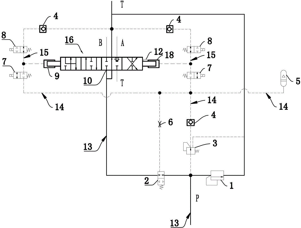
[0019] figure 1 An electro-hydraulic control device for a hydraulic distributor of a tractor suspension mechanism is shown, and an oil inlet 10 of a hydraulic distributor 16 is connected to a host oil circuit 13 . The two ends of the valve stem of the hydraulic distributor 16 are respectively connected to the first hydraulic push rod 9 and the second hydraulic push rod 18, and the first hydraulic push rod 9 and the second hydraulic push rod 18 are respectively connected to the hydraulic distributor through an electromagnetic switch valve a8. The oil return circuit, the first hydraulic push rod 9 and the second hydraulic push rod 18 are respectively connected to an energy storage oil circuit 14 through an electromagnetic switch valve b7, the energy storage oil circuit 14 is provided with an accumulator 5, and the host oil circuit 13 passes through The pressure reducing valve 3 and the one-way valve 4 connected in sequence are connected to the energy storage oil circuit 14, and ...

Embodiment 2

[0028] Such as figure 2 As shown, the structure of this embodiment is basically the same as that of Embodiment 1, the difference is that an electromagnetic switch valve c17 is set between the oil return circuit of the hydraulic distributor 16 of the hydraulic control port of the two-position two-way hydraulic control valve 2, and the storage A pressure switch 11 is arranged on the energy oil passage 14, and the pressure switch 11 is electrically connected with the solenoid valve c17. The effect of such setting is to further improve the response sensitivity and reliability of the system.

[0029] When the pressure in the energy storage oil circuit 14 drops to the set value, the pressure switch 11 drives the electromagnetic switch valve c17 to act, so that the hydraulic control port of the two-position two-way hydraulic control valve 2 is connected to the return oil circuit. 6, the oil pressure of the hydraulic control port drops instantly, and the two-position two-way hydraul...


PUM


Abstract

The invention relates to the field of hydraulic technology, in particular to an electro-hydraulic control device for a hydraulic distributor. An electro-hydraulic control device for a hydraulic distributor. The oil inlet of the hydraulic distributor is connected to the host oil circuit. The two ends of the valve stem of the hydraulic distributor are respectively connected to hydraulic push rods. The oil return circuit of the distributor is connected to an energy storage oil circuit through the electromagnetic switch valve b, the electromagnetic switch valve a and the electromagnetic switch valve b are connected in series, and the control oil circuit formed between the two is respectively connected to the power input port of the hydraulic push rod , there is an accumulator on the energy storage oil circuit, and the host oil circuit is connected to the energy storage oil circuit through the connected pressure reducing valve and check valve; The element is connected with the energy storage oil circuit; the hydraulic push rod is provided with a displacement sensor, and the displacement sensor is controlled by an electronic control unit. The invention has the beneficial effects of high control precision, fast execution speed, safety and reliability, and convenient use.

Description

technical field [0001] The invention relates to the field of hydraulic technology, in particular to an electro-hydraulic control device for a hydraulic distributor. Background technique [0002] At present, hydraulic distributors are generally operated manually, and are controlled by purely mechanical actuators. The execution response is lagging, the accuracy is poor, the adjustment and calibration are cumbersome, and it is inconvenient to use. Automation and intelligence cannot be realized through electronic control technology. [0003] The electronically controlled distributor announced in Chinese utility model patent ZL201120420692.7 uses an electromagnet or a motor and a screw nut mechanism as a linear actuator, and the valve stem of the distributor is manipulated to move up, down, neutral, and floating through a sensor and an electronic control unit. Wait for the set position to realize the intelligent control of the hydraulic lifter. However, it requires a lot of ene...

Claims


Application Information

Patent Timeline
Patent Type & Authority Patents(China)
IPC IPC(8): F15B13/02
Inventor 孙军孙勇王秀强吴贝贝于洪波任照龙楚涛
Owner 潍坊威度电子科技有限公司
Why Eureka
Try Eureka