Rotating connector, pipe winder and engineering machine

A technology of rotary joints and reels, which is applied in the direction of pipes/pipe joints/fittings, mechanical equipment, adjustable connections, etc. It can solve problems such as core deformation, unreliable structure of rotary joints, and complicated connections.

Inactive Publication Date: 2013-04-17
SANY HEAVY IND CO LTD (CN)
View PDF4 Cites 6 Cited by
  • Summary
  • Abstract
  • Description
  • Claims
  • Application Information

AI Technical Summary

Problems solved by technology

[0003] At present, on the one hand, when the existing rotary joint is used for the hydraulic hose reel, it is highly interdependent with the main structure of the hydraulic hose reel, and the structure is not independent. The connection, the connection is more complicated, and the processing and assembly of the core with the oil channel of the rotary joint itself is relatively cumbersome
[0004] On the other hand, the core and the jacket of the rotary joint are not directly fixed, the structure of the rotary joint is not reliable, and the core is subject to a large bending moment during work, which has an adverse effect on the sealing between the core and the jacket, and also has a negative impact on the shaft. The strength requirements are higher; in addition, the entry hole of the core is set on one side, and the reaction force of the liquid flow will produce a radial force on the axis of the core during work, causing the core to deform. After the core is deformed, the rotation work will be affected. The impact of the liquid flow is greater, forming a vicious circle, and eventually the core is scrapped

Method used


Image

  • Rotating connector, pipe winder and engineering machine

Examples


Embodiment Construction

[0033] It should be noted that, in the case of no conflict, the embodiments of the present invention and the features in the embodiments can be combined with each other. The present invention will be described in detail below with reference to the accompanying drawings and examples.

[0034] Below in conjunction with accompanying drawing, embodiment of the present invention is described in further detail:

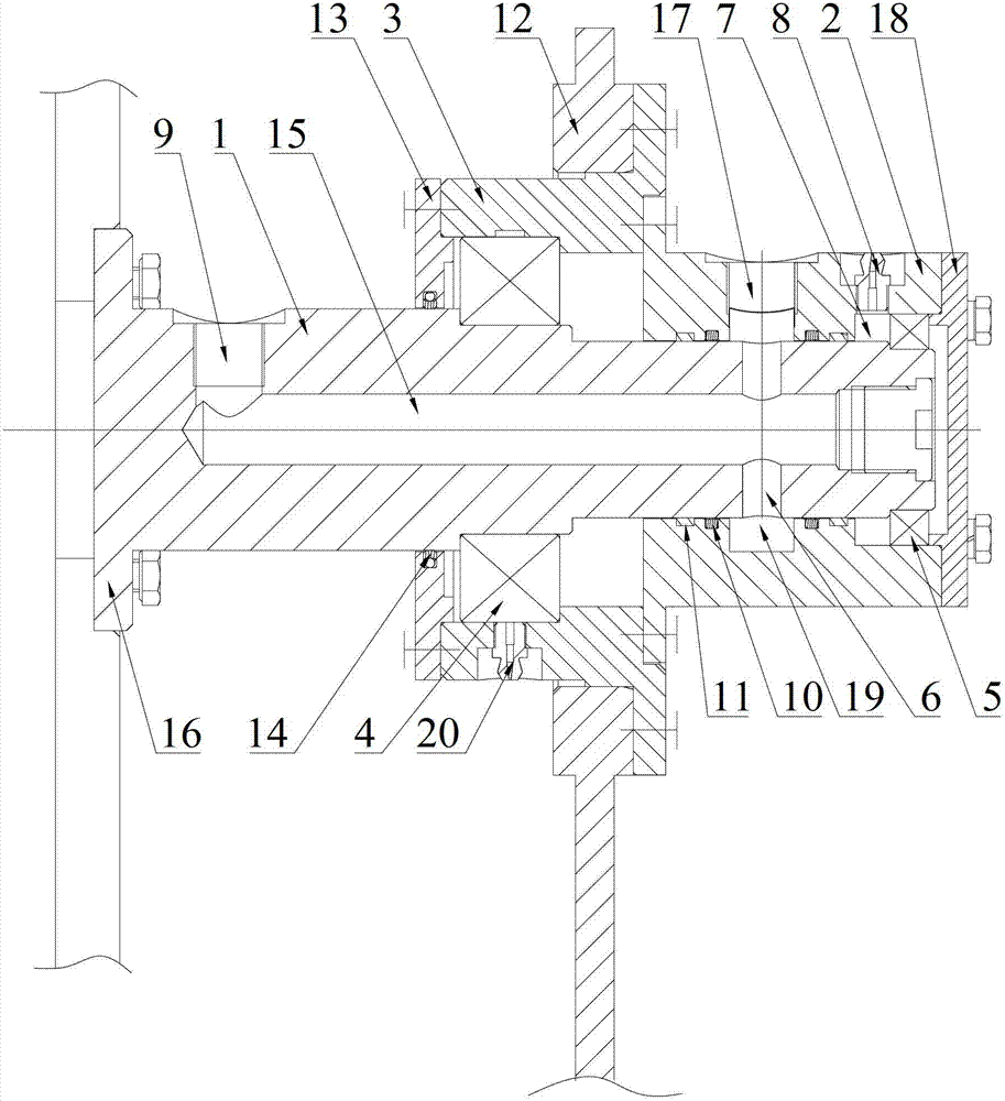
[0035] Such as figure 1 Shown is the rotary joint provided by the embodiment of the present invention, including the outer casing 2 and the core 1, wherein the outer casing 2 is used to be fixedly arranged on the support 12, and has a liquid inlet hole 17; the core 1 is rotatably embedded In the jacket 2, it has a first end, a second end and a liquid passage 15; the first end is provided with a liquid inlet 6, and the liquid inlet 6 corresponds to the position of the liquid inlet 17 of the jacket 2; the second end is provided with a The liquid outlet hole 9; the liquid pa...


PUM


Abstract

The invention discloses a rotating connector, a pipe winder and an engineering machine. The rotating connector comprises a jacket and a core; the jacket is used for being fixedly arranged on a support and is provided with a liquid inlet hole; the core is rotatably embedded in the jacket and is provided with a first end, a second end and a liquid flowing cavity; the first end is provided with a liquid inlet hole, and the liquid inlet hole of the core corresponds to the liquid inlet hole of the jacket; a liquid outlet hole is arranged at the second end; the liquid inlet hole of the core is communicated with the liquid outlet hole via the liquid flowing cavity; and the liquid inlet hole of the core is a through hole transversely penetrating through the core, and an annular cavity is arranged between the liquid inlet hole of the jacket and the liquid inlet hole of the core and is arranged on the jacket and / or the core. The liquid inlet hole of the core of the rotating connector is the through hole, fluid is prevented from exerting radial acting force on the core, and the rotating connector is fixedly arranged on the support firmly and stably via the jacket directly. Accordingly, the rotating connector is not easy to deform, and the service life of the rotating connector is prolonged. Besides, the rotating connector is an independent module, and accordingly is easy to assemble.

Description

technical field [0001] The invention relates to the mechanical field, in particular to a rotary joint, a hose reel and engineering machinery. Background technique [0002] The swivel joint is mainly used for hydraulic hose reels. The reel of the hydraulic hose reel is rotatably set on the support frame. One end of the swivel joint is connected to the pipeline wound on the reel and rotates with the reel. The other end is connected with the reel. Connect the stationary line so that the hydraulic hose reel is able to deploy or retract the hydraulic line while simultaneously delivering fluid through the line. Therefore, the swivel joint plays a key role in the hydraulic hose reel. [0003] At present, on the one hand, when the existing rotary joint is used for the hydraulic hose reel, it is highly interdependent with the main structure of the hydraulic hose reel, and the structure is not independent. The connection, the connection is relatively complicated, and the processing ...

Claims


Application Information

Patent Timeline
Patent Type & Authority Applications(China)
IPC IPC(8): F16L27/087B65H75/38
Inventor 李勇刘志岩崔亚东
Owner SANY HEAVY IND CO LTD (CN)
Why Eureka
Try Eureka