Fusion structure of missile wing connection lug channel and missile body

A technology for connecting ears and wings, applied to projectiles, offensive equipment, weapon types, etc., can solve problems such as uneven force, excessive force on fasteners, difficulty in ensuring ear slots and body, and reduce Effects of interfering with drag and wave drag, increasing wing lift surface, and improving wing load distribution

Inactive Publication Date: 2013-04-17
JIANGXI HONGDU AVIATION IND GRP
View PDF5 Cites 3 Cited by
  • Summary
  • Abstract
  • Description
  • Claims
  • Application Information

AI Technical Summary

Problems solved by technology

Most of the lightweight aluminum materials used for the missile body have poor welding performance and are easily deformed after welding
The lugs are riveted or screwed to the bomb body, and the load on the bomb is transmitted to the wing-body joint through rivets or screws. Due to inconsistent fixing tightness and uneven force, it is easy to cause excessive force on some fasteners to wear and deform even broken
The lug grooves are assembled on the bomb body, no matter what kind of process is used, even if there is a frame tooling, it is difficult to guarantee the relative position accuracy requirements of the lug grooves and the body, that is, the wings and the body

Method used


Image

  • Fusion structure of missile wing connection lug channel and missile body
  • Fusion structure of missile wing connection lug channel and missile body

Examples


Embodiment Construction

[0014] The present invention will be further described below in conjunction with the drawings and specific embodiments.

[0015] The following embodiments are only used to illustrate the present invention, and are not used to limit the protection scope of the present invention.

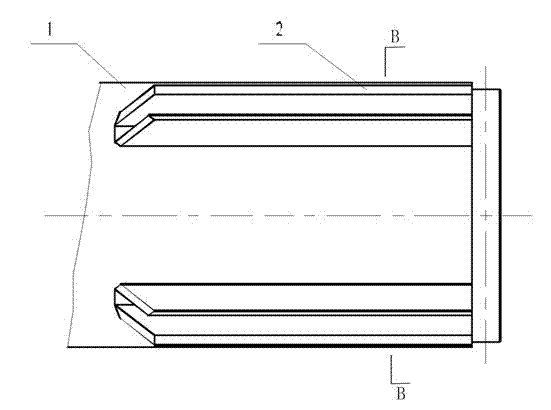
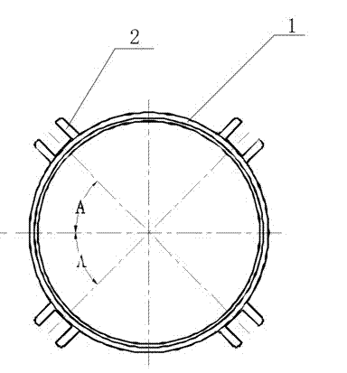
[0016] Such as figure 1 with 2 As shown, an elastic wing connecting ear groove and elastic body fusion structure of the present invention, the fusion structure adopts the elastic body 1 and the ear groove 2 to be directly CNC integrated and formed. The elastic body 1 is made of aluminum, and the central axis of the ear groove 2 is The included angle of the axis of the projectile body is A, A=45°±12'.

[0017] The bullet body 1 uses a special-shaped aluminum tube blank with ribs. The inner and outer diameter coaxiality of the bullet body 1 is required to be 0.08. The parts are processed by the overall CNC machine, the dimensional accuracy is easy to control, the process is simple, and the surface quality is g...


PUM


Abstract

The invention discloses a fusion structure of a missile wing connection lug channel and a missile body. The fusion structure is formed by direct numerical control integration processing of the missile body and the lug channel. The missile wing connection lug channel and the missile body are integrally designed and fused, an appropriate aluminum sectional material is selected, the missile body and lug channel are directly finished by numerical control processing, an assembly link is not required, a connection tool is omitted, working efficiency is improved, and parallel operation is facilitated.

Description

Technical field [0001] The invention relates to a fusion structure of a projectile wing connecting ear groove and a projectile body, belonging to the field of projectile body structure design. Background technique [0002] During the flight of the missile, the missile body not only has to bear the local aerodynamic force acting on its surface, the mass force of the structure itself, and the mass forces of the various parts of the missile body, but also bear the greater concentration of the missile wings, tail and other parts through the fixed joints. Load. The local aerodynamic force on most surfaces of the projectile body is relatively small, and is approximately symmetrically distributed along the circumference of the projectile body cross-section, which can basically balance itself without being transmitted to other parts of the projectile body. The components are basically symmetrical according to the plane of symmetry of the projectile body. Distribution, its mass force can...

Claims


Application Information

Patent Timeline
Patent Type & Authority Applications(China)
IPC IPC(8): F42B10/04
Inventor 万渠王武曾晓建王艳丽董皓葳毛端华王克强陈龙
Owner JIANGXI HONGDU AVIATION IND GRP
Why Eureka
Try Eureka