
Image processing method

An image processing and image technology, applied in the field of image processing, can solve the problem of data matching processing time and other problems

Active Publication Date: 2013-04-17
HONDA MOTOR CO LTD
View PDF4 Cites 4 Cited by
  • Summary
  • Abstract
  • Description
  • Claims
  • Application Information

AI Technical Summary

Problems solved by technology

Moreover, the data matching process takes a long time

Method used


Image

  • Image processing method
  • Image processing method
  • Image processing method

Examples


Embodiment Construction

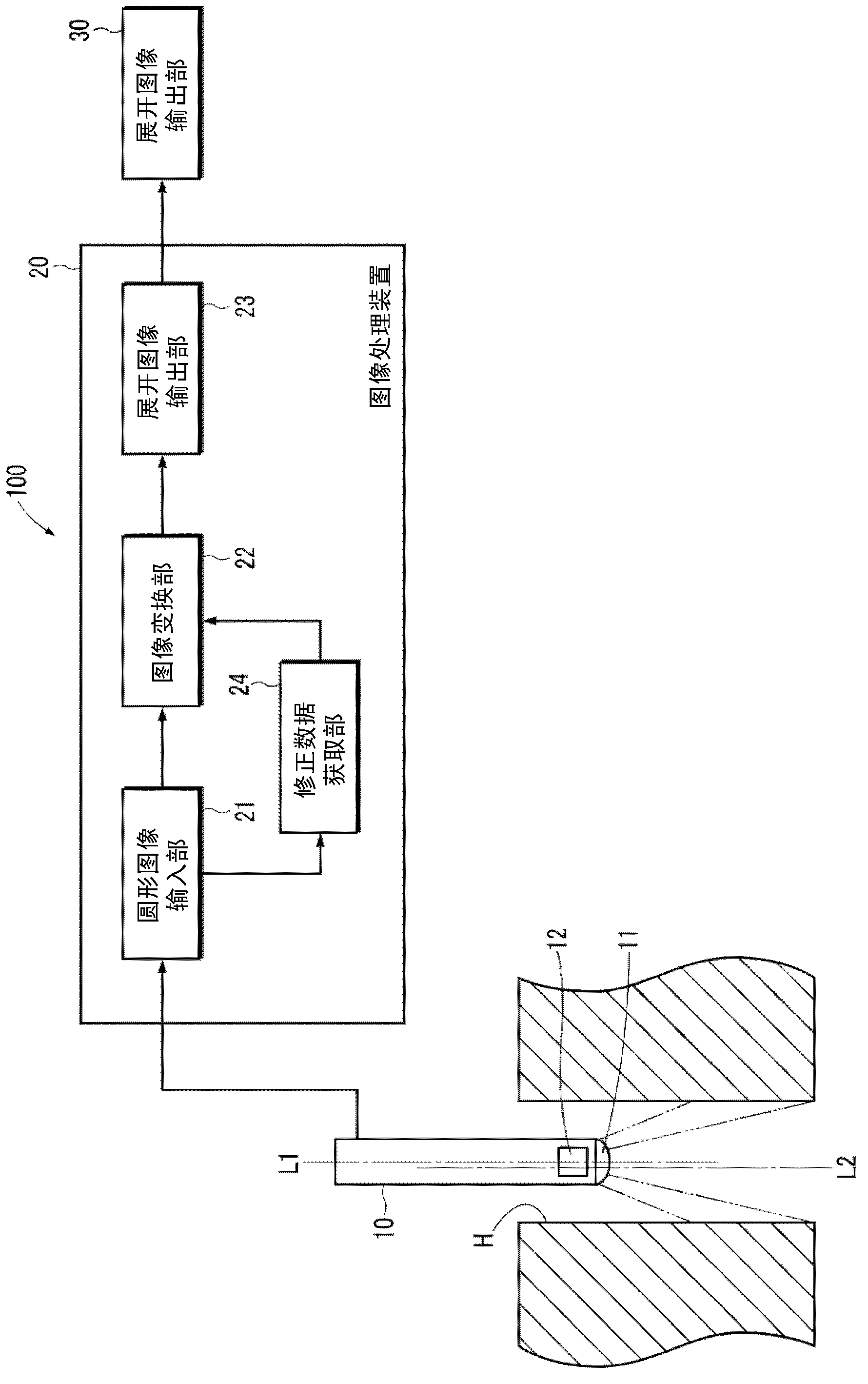
[0017] Embodiments of the present invention will be described with reference to the drawings. here, as figure 1 As shown, an example will be described in which the side wall surface in the hole H (hereinafter also referred to as the hole wall surface) as the object to be photographed is photographed from above by the omnidirectional imaging system 100 .

[0018] In addition, the hole H may be, for example, a hole for providing a fuel injection device (injector). However, its use, shape, pore size, and depth are not limited. For example, the hole H may be a through hole or a hole having a bottom surface. In addition, the hole H may be a straight hole with a constant diameter, or a tapered hole with a gradually changing diameter.

[0019] The omnidirectional imaging system 100 is composed of an omnidirectional imaging device 10 , an image processing device 20 , and a display device 30 .

[0020] The omnidirectional imaging device 10 captures images of the side wall surface o...


PUM


Abstract

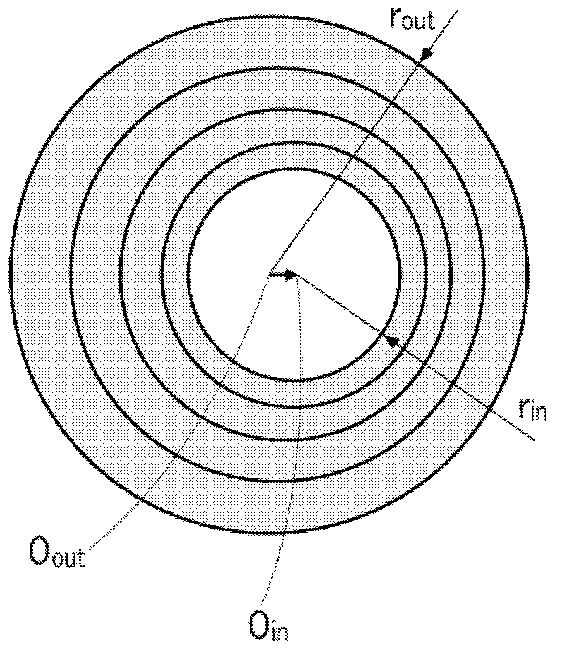
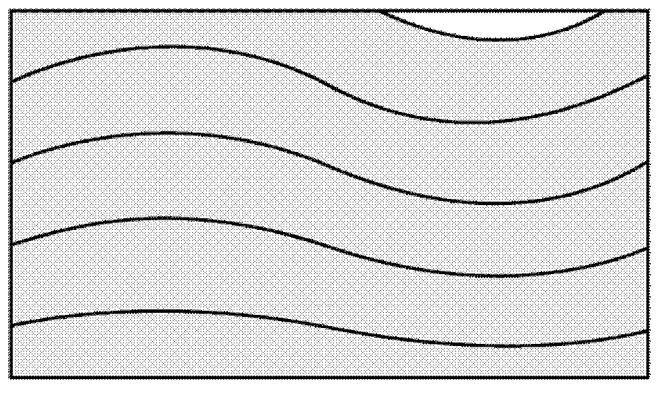
An image processing method includes a step of extracting an inner circle and an outer circle from an annular image, a step of obtaining the center for the extracted inner circle and the extracted outer circle respectively, and a step of moving a processing center serving as a reference in the polar coordinate conversion gradually between the center of the inner circle and the center of the outer circle to convert the circular image into a panoramic development image. According thereto, when an annular image of a side wall surface of a hole imaged by an omnidirectional imaging device (10) is converted into a panoramic development image according to a polar coordinate conversion, a distortion resulted from a position deviation occurred between an optical axis (L1) of the omnidirectional imaging device (10) and a central axis (L2) of the hole (H) can be corrected.

Description

technical field [0001] The present invention relates to an image processing method, particularly a correction method for converting a circular image into a panorama image. Background technique [0002] In the prior art, an omnidirectional imaging device such as an endoscope is used to photograph the side wall surface of the hole, and defects, damage, etc. are inspected based on the photographed image. At this time, a general method is to convert the captured circular image into a panorama expanded image. [0003] When such conversion is performed, when the optical axis of the omnidirectional imaging device deviates from the central axis of the hole, correction processing is required. As such correction processing, Japanese Patent Application Laid-Open No. 2000-331168 discloses that when a camera captures images of the inner surface of the conduit, data matching processing is performed to obtain the deviation between the optical axis of the camera and the central axis of the...

Claims


Application Information

Patent Timeline
Patent Type & Authority Applications(China)
IPC IPC(8): G01N21/88
CPCG01N21/954
Inventor 及川聪大久保岩谦
Owner HONDA MOTOR CO LTD
Learn More