Conducting wire rounding die

A wire and mold technology, applied in the field of wire rounding molds, can solve problems such as poor rounding effect, difficulty in cold crimping, and broken wires

Inactive Publication Date: 2013-04-17
WUJIANG TRANSFORMER
View PDF7 Cites 7 Cited by
  • Summary
  • Abstract
  • Description
  • Claims
  • Application Information

AI Technical Summary

Problems solved by technology

Generally, low-voltage coils are wound with transposed wires, and once the transposed wires are scattered, it is difficult to effectively insert the coil head into the terminal, and it is difficult to achieve cold crimping. It is necessary to tighten the loose coil head before inserting it. Terminals
The upper and lower molds in the traditional compression mold are semicircular, and the rounding effect is not good, and the wires are prone to broken roots and wires

Method used


Image

  • Conducting wire rounding die
  • Conducting wire rounding die
  • Conducting wire rounding die

Examples


Embodiment Construction

[0015] The preferred embodiments of the present invention will be described in detail below in conjunction with the accompanying drawings, so that the advantages and features of the present invention can be more easily understood by those skilled in the art, so as to define the protection scope of the present invention more clearly.

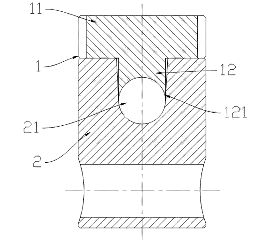
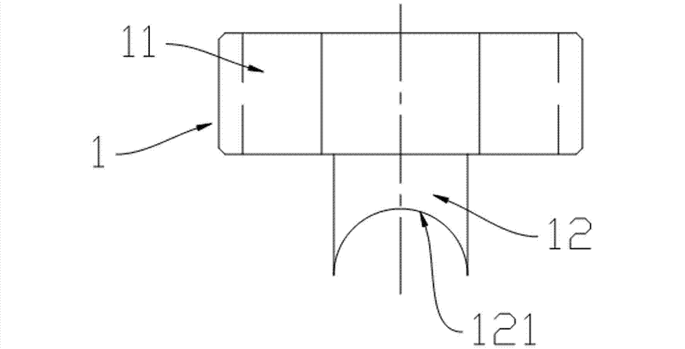
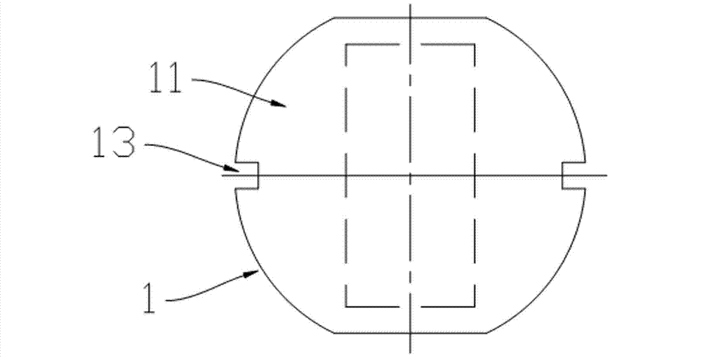
[0016] as attached figure 1 As shown, the invention discloses a wire rounding die, which is used for pressing the wire into a circular shape.

[0017] The wire rounding mold includes an upper mold 1 and a lower mold 2. as attached figure 1 As shown, the upper mold 1 is at the top, and the lower mold 2 is at the bottom. The upper mold 1 can slide relative to the lower mold 2 to realize mold closing and mold opening. When the upper mold 1 and the lower mold 2 are in the mold opening state, the parts forming the cavity between the upper mold 1 and the lower mold 2 are separated from each other. When the mold 1 and the lower mold 2 are in ...


PUM

PropertyMeasurementUnit
angleaaaaaaaaaa

Abstract

The invention discloses a conducting wire rounding die, which is used for pressing a conducting wire to be round. The conducting wire rounding die comprises an upper die and a lower die. The upper die comprises a body and a protruding part which downwards protrudes relative to the body. A circular-arc groove with a downward opening is arranged at the lower part of the protruding part. The cross section of the circular-arc groove in the length direction perpendicular to the protruding part is circular-arc-shaped. An open groove with an upward opening is arranged at the upper part of the lower die. When the upper die and the lower die are closed, the open groove contains the protruding part of the upper die, and the open groove and the circular-arc groove form a round cavity. By adopting the structure, scattered coil outgoing ends can be pressed to be round and tightened, so that the coil outgoing ends can be very easily inserted into a wiring terminal and an ideal pressure welding effect is achieved.

Description

technical field [0001] The invention relates to a wire rounding mold. Background technique [0002] As the capacity of the transformer increases, the requirements for the manufacturing process of the transformer become stricter, and slight negligence may cause accidents in the operation of the transformer. In the past, the phosphor copper welding process was used to connect the transformer wires and wires. During the welding process, black smoke will be generated, which will pollute the transformer body. At the same time, the welding slag and burrs generated at the same time are difficult to remove, which may easily cause the partial discharge of the transformer to fail. A more reasonable and reliable connection method is needed. Nowadays, the cold crimping method is used to realize the connection between the coil head and the wire. Generally, low-voltage coils are wound with transposed wires, and once the transposed wires are scattered, it is difficult to effectively inser...

Claims


Application Information

Patent Timeline
Patent Type & Authority Applications(China)
IPC IPC(8): H01R43/28H01F27/29
Inventor 马健花虹钮绣荣金健
Owner WUJIANG TRANSFORMER
Why Eureka
Try Eureka