Supercharge Your Innovation With Domain-Expert AI Agents!

Method of double-sided friction stir welding of metal plates with gaps in butt joints

A technology of friction stir and joining method, which is applied in the direction of metal processing, metal processing equipment, welding/welding/cutting items, etc., and can solve problems such as layer difference

Active Publication Date: 2015-08-05
PRIMETALS TECHNOLOGIES JAPAN LTD
View PDF17 Cites 0 Cited by
  • Summary
  • Abstract
  • Description
  • Claims
  • Application Information

AI Technical Summary

Problems solved by technology

[0004] On the other hand, there are cases where it is necessary to join two metal plates having different plate thicknesses. In this case, a step difference occurs at the butted portion of the two metal plates.

Method used


Image

  • Method of double-sided friction stir welding of metal plates with gaps in butt joints
  • Method of double-sided friction stir welding of metal plates with gaps in butt joints
  • Method of double-sided friction stir welding of metal plates with gaps in butt joints

Examples


no. 1 approach

[0115] First, use Figure 1 to Figure 9 A first embodiment of the present invention will be described. This embodiment is an embodiment in which the present invention is applied to joining of two metal plates having the same plate thickness.

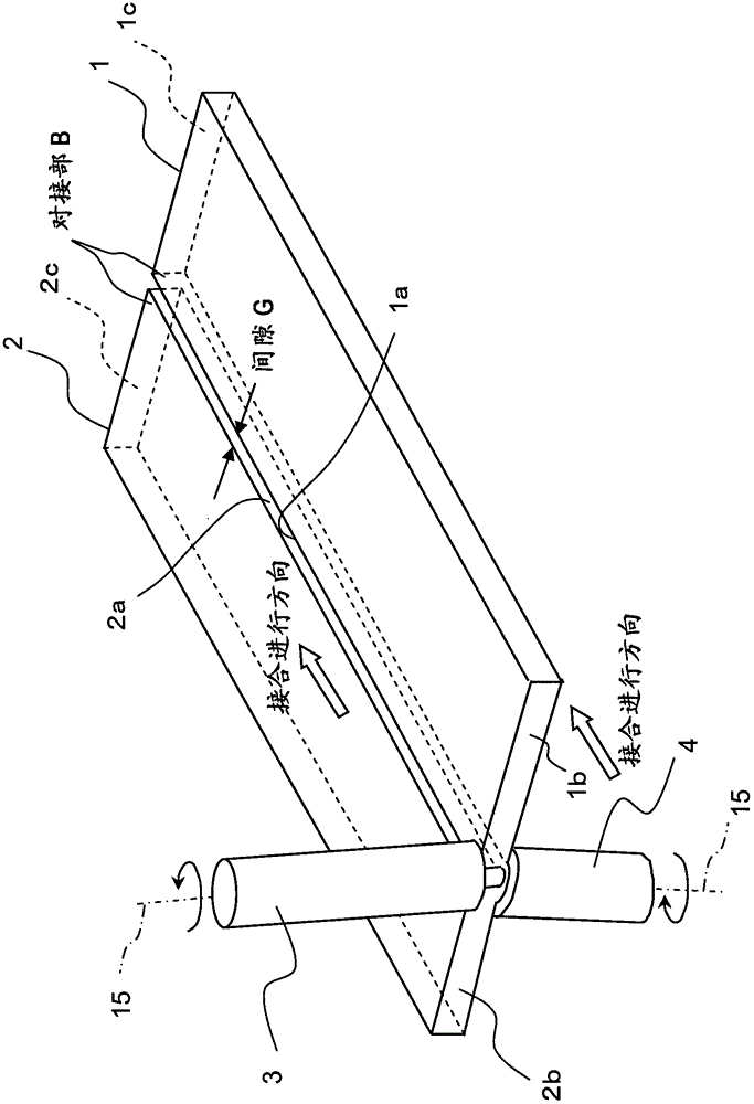
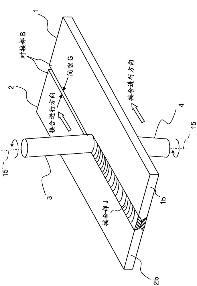
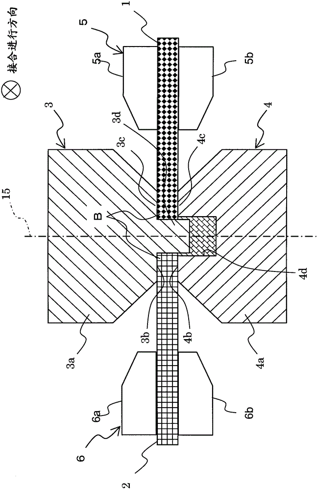
[0116] Figure 1 to Figure 5 is a diagram showing a double-sided friction stir welding method according to the first embodiment of the present invention, figure 1 It is a perspective view of the state after the joining start, figure 2 It is a perspective view of the joining state, image 3 is a cross-sectional view perpendicular to the tool movement direction in the state of joining, Figure 4 It is a cross-sectional view in a direction perpendicular to the tool moving direction in a joined state where the cross-sectional positions of the metal plate and the rotary tool are shifted, Figure 5 It is a cross-sectional view showing the dimensional relationship between the first and second rotary tools.

[0117] like figure 1 as wel...

no. 2 approach

[0187] Next, a second embodiment of the present invention will be described. This embodiment is an embodiment in which the present invention is applied to the joining of two metal plates having different plate thicknesses.

[0188] Figure 10 It is a figure which shows the double-sided friction stir welding method of the 2nd Embodiment of this invention, and is the state in which it is joining image 3 Sectional view at right angles to the same tool movement direction. In the figure, for image 3 The same components are provided with the same reference numerals.

[0189] Figure 10 Among them, the two metal plates 1 and 2 have different thicknesses, and a level difference is formed at the butt joint B. First, a case where the shaft centers 15 of the first and second rotary tools 3 and 4 are not inclined will be described.

[0190]When two metal plates having different thicknesses are subjected to friction stir welding simultaneously from both sides according to the prese...

Embodiment 1

[0197] (The inclination angle of the tool moving direction is the same up and down)

[0198] Metal plate 1 (5052 aluminum alloy with a plate thickness of 1 mm) and metal plate 2 (5052 aluminum alloy with a plate thickness of 2 mm) were butt-jointed. The positional relationship between the first and second rotary tools 3, 4 and the metal plates 1, 2 in Embodiment 1 is as follows Figure 11 shown. Figure 11 It is a cross-sectional view of the tool movement direction in the state of joining. Cross-sectional view perpendicular to the direction of tool movement in the state of joining, and the above-mentioned case where the rotating tool is not tilted Figure 10 same. The metal plates 1 and 2 are installed so that no step occurs on the back surface of the butt portion B. As shown in FIG.

[0199] The dimensions of the first and second rotary tools used in the confirmation test are as follows. The diameter of the shoulder surface 3 b of the first rotary tool 3 is 8 mm, the dia...


PUM


Abstract

To perform double-side friction stir welding whereby even when the gap between abutting portions of two metal plates exceeds 0.5 mm, the welding strength is increased by suppressing the welding failure, the economy is improved by suppressing the increase in facility cost, and the production efficiency is improved. First and second rotating tools (3, 4) respectively have tool main bodies (3a, 4a). Shoulder portions (3c, 4c) are respectively formed at the tip portions of the tool main bodies (3a, 4a). The first rotating tool (3) further includes a protruding portion (3d) formed to protrude from the tip portion of the tool main body. The second rotating tool (4) further includes a recessed portion (4d) formed in the tip portion of the tool main body and accommodating the tip of the protruding portion (3d) upon welding of two metal plates (1, 2). In a state where the gap shorter than the diameter of the protruding portion is generated between abutting portions (B) obtained by causing the end faces of the metal plates (1, 2) to face each other, the metal plates (1, 2) are gripped by gripping devices (5, 6), the tip of the protruding portion (3d) of the rotating tool is inserted into the recessed portion (4d) of the rotating tool, and the metal plates are welded by friction-stirring the entire areas of the abutting portions in the plate thickness direction.

Description

technical field [0001] The present invention relates to a double-side friction stir welding method of friction stirring a joint portion of metal plates having a gap in a butt joint portion from both sides and joining them. Background technique [0002] There is known a friction stir welding technique in which the surface of a shoulder portion provided on the tool body of the rotary tool is brought into contact with the surface of a joint member while rotating the rotary tool, and the surface of the shoulder portion and the joint member are used to contact each other. The frictional heat of the surface performs friction stirring, and the materials are stirred and joined while the joining member is in a solid state below the melting point. This joining technology mainly uses aluminum alloys and is being put into practical use in various industrial fields. [0003] When the butt end faces of the two metal plates to be friction stir welded are not machined surfaces but are shea...

Claims


Application Information

Patent Timeline
Patent Type & Authority Patents(China)
IPC IPC(8): B23K20/12
CPCB23K20/2336B23K20/122B23K2203/10B23K2201/18B23K20/126B23K20/1255B23K2101/18B23K2103/10
Inventor 加贺慎一小野濑满富永宪明斋藤武彦芳村泰嗣平野聪朴胜焕
Owner PRIMETALS TECHNOLOGIES JAPAN LTD
Features
  • R&D
  • Intellectual Property
  • Life Sciences
  • Materials
  • Tech Scout
  • Unparalleled Data Quality
  • Higher Quality Content
  • 60% Fewer Hallucinations
Learn More