Rotatable anvil block structure

A technology of anvils and support seats, which is applied in the direction of manufacturing tools, forging/pressing/hammer devices, forging/pressing/hammering machinery, etc., can solve the problem of inability to rotate large workpieces, improve the billet making process, and facilitate operation , the effect of improving organizational performance

Active Publication Date: 2013-04-24
WUXI TURBINE BLADE
View PDF5 Cites 8 Cited by
  • Summary
  • Abstract
  • Description
  • Claims
  • Application Information

AI Technical Summary

Problems solved by technology

[0003] In view of the above problems, the present invention provides a rotatable anvil structure, which can solve the problem that the existing fixed free forging anvil cannot rotate large workpieces

Method used


Image

  • Rotatable anvil block structure
  • Rotatable anvil block structure
  • Rotatable anvil block structure

Examples


Embodiment Construction

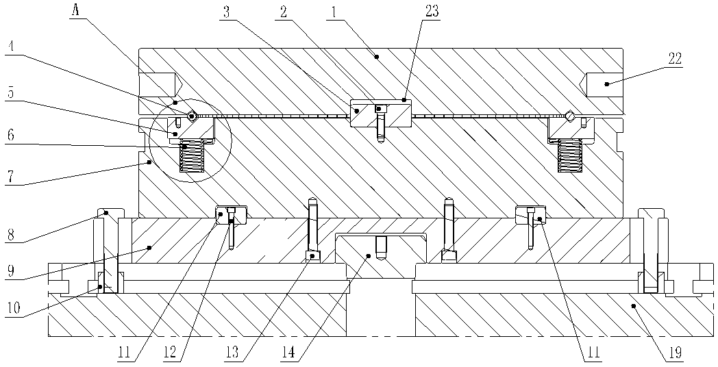
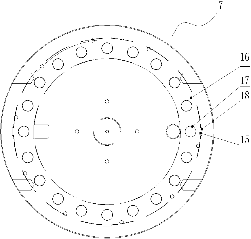
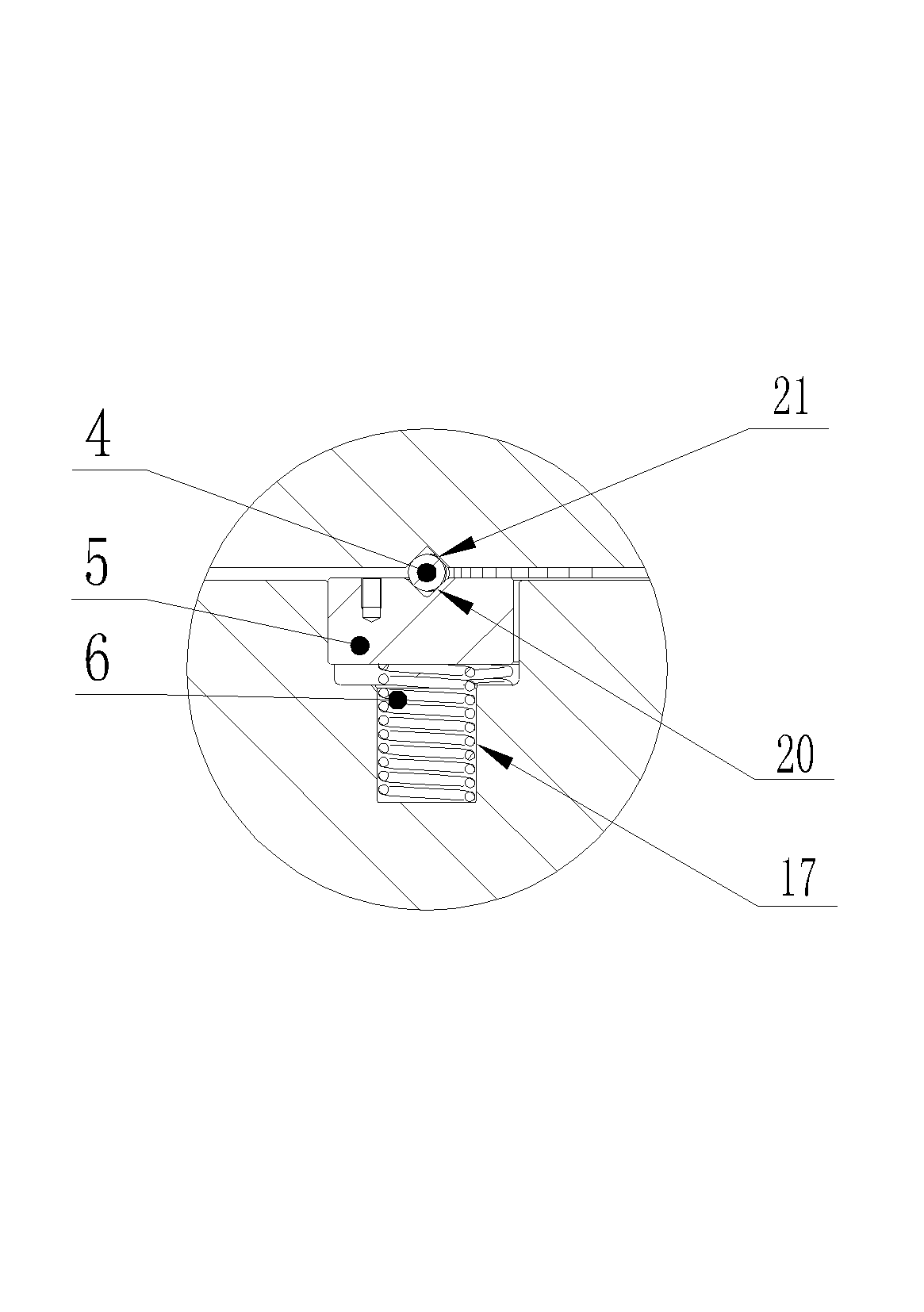
[0017] See figure 1 , figure 2 and image 3 The structure of the present invention includes a base plate 9 and a rotating platform 1. The base plate 9 is installed on the equipment mobile platform 19. A support seat 7 is fixedly installed on the base plate 9. An annular groove 16 is opened on the plane of the support seat 7, and an annular groove 16 is installed in the annular groove 16. Annular slideway 5, the upper plane of annular slideway 5, the lower plane of rotating platform 1 correspondingly have a V-shaped groove 20, 21 respectively, in the V-shaped groove 20 of annular slideway 5, a ring of steel balls 4 is tightly filled, and the rotation The platform 1 is supported by the steel ball 4 in the V-shaped groove 20 of the annular slideway, and the V-shaped groove 21 on the lower plane of the rotating platform 1 is fastened on the steel ball 4, and a horizontal blind hole 22 is opened on the outer peripheral surface of the rotating platform 1 . The center of the upper...


PUM


Abstract

The invention provides a rotatable anvil block structure and solves the problem that the existing fixed type free anvil block cannot rotate a large-sized work piece. The rotatable anvil block structure comprises a bottom plate; and the bottom plate is mounted on an equipment moving platform. The rotatable anvil block structure is characterized by further comprising a rotatable platform; the bottom plate is fixedly provided with a supporting base; an annular groove is arranged on the upper plane of the supporting base; the annular groove is internally provided with an annular slide way; a V-shaped groove is correspondingly arranged on each of the upper plane of the annular slide way and the lower plane of the rotatable platform; the V-shaped groove of the annular slide way is internally and tightly filled with a ring of steel beads; the rotatable platform is supported by the steel beads in the V-shaped groove of the annular slide way and the V-shaped groove of the lower plane of the rotatable platform is buckled on the steel beads; and horizontal bind holes are formed in the outer circumference of the rotatable platform.

Description

technical field [0001] The invention relates to the field of tooling structures for free forging blanks, in particular to a rotatable anvil block structure. Background technique [0002] Usually free forging anvils are integrally processed and manufactured by castings or forgings, and are assembled through dovetail grooves and wedge irons, and the anvils are fixed when in use. Its disadvantages are: when large-scale free forging is formed, workers cannot manually rotate the workpiece due to the heavy weight of the workpiece, and even with an operating machine, the workpiece cannot be rotated 90° before forging, which directly affects the forging time and final forging The temperature control will also increase the number of forging fires, which not only limits the billet making process to a great extent, but also has a serious impact on the microstructure and properties of the workpiece. Contents of the invention [0003] In view of the above problems, the present inventi...

Claims


Application Information

Patent Timeline
Patent Type & Authority Applications(China)
IPC IPC(8): B21J13/06
Inventor 王治平吴德振张建国
Owner WUXI TURBINE BLADE
Why Eureka
Try Eureka