Stiffness compensation device for remanufactured cantilever beam of heavy-duty machine

A technology for heavy-duty machine tools and compensating devices, used in manufacturing tools, other manufacturing equipment/tools, etc., can solve the problems of large structure size of cantilever beams, distortion and vibration, and insufficient rigidity, so as to reduce the workload of machine tool assembly and strengthen Stiffness, the effect of enhancing the ability to resist deformation in the vertical direction

Active Publication Date: 2013-04-24
CHONGQING UNIV
View PDF5 Cites 2 Cited by
  • Summary
  • Abstract
  • Description
  • Claims
  • Application Information

AI Technical Summary

Problems solved by technology

However, the remanufactured cantilever beams in heavy-duty machine tools have large structural dimensions and large spans, which are prone to bending deformation and vibration during processing
For such cantilever beams installed on heavy machine tools after remanufacturing, it is necessary to solve the problem of insufficient rigidity

Method used


Image

  • Stiffness compensation device for remanufactured cantilever beam of heavy-duty machine
  • Stiffness compensation device for remanufactured cantilever beam of heavy-duty machine
  • Stiffness compensation device for remanufactured cantilever beam of heavy-duty machine

Examples


Embodiment Construction

[0020] The present invention will be further described below in conjunction with the accompanying drawings and embodiments, but it should not be understood that the scope of the subject matter of the present invention is limited to the following embodiments. Without departing from the above-mentioned technical idea of ​​the present invention, various replacements and changes made according to common technical knowledge and customary means in this field shall be included in the scope of the present invention.

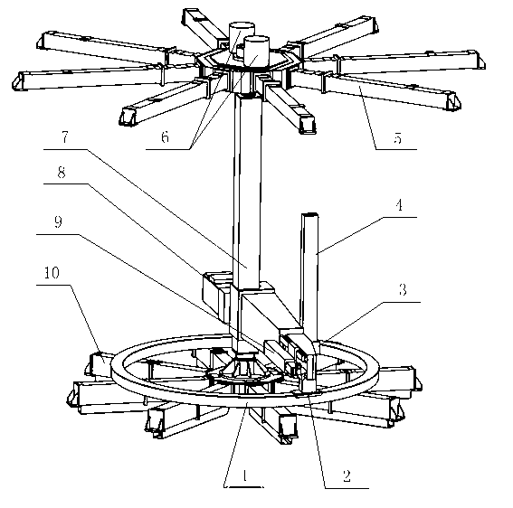
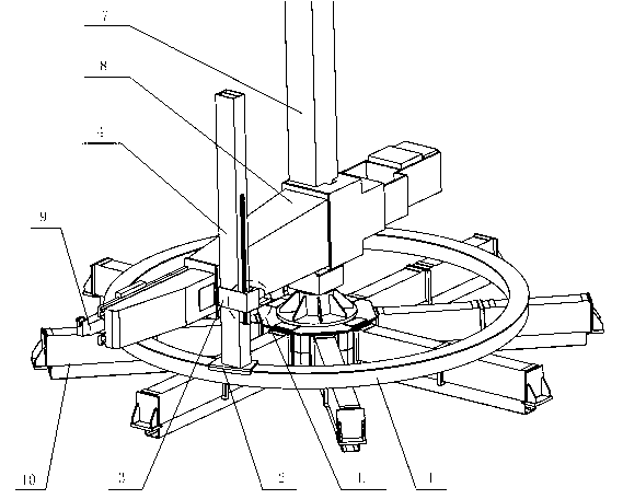
[0021] See the accompanying drawings: a heavy-duty machine tool remanufacturing cantilever beam stiffness compensation device, including arc guide rail 1 and auxiliary column 4 installed on the heavy-duty machine tool.

[0022] The heavy-duty machine tool mainly includes a main column 7 , a cantilever beam 8 , a lower support frame 10 and an upper support frame 5 . The main column 7 is installed perpendicular to the ground, and its upper and lower ends are connected to t...


PUM


Abstract

The invention aims to provide a device which can increase stiffness of a remanufactured cantilever beam of a heavy-duty machine without modifying primary structure of the heavy-duty machine and slightly increasing primary weight of the heavy-duty machine, particularly relates to a stiffness compensation device for the remanufactured cantilever beam of the heavy-duty machine. The stiffness compensation device comprises an arc guide rail and an auxiliary column which are arranged on the heavy-duty machine. The heavy-duty machine mainly comprises a main column, the cantilever beam, lower supports and upper supports. The main column is installed perpendicularly to the ground. A plurality of the lower supports are radially arranged around a shaft sleeve of a rotating shaft at the lower end of the main column, and the cantilever beam is arranged on the main column which drives a knife rest to move circularly when rotating; the arc guide rail is arranged on a supporting platform composed of a plurality of lower supports, the auxiliary column is parallel to the main column while being perpendicular to the cantilever beam; and a sliding block mounted on the arc guide rail is arranged at the lower end of the auxiliary column.

Description

technical field [0001] The invention relates to the field of heavy-duty machine tool manufacturing, in particular to a heavy-duty machine tool for processing large-scale ring-shaped parts and having a cantilever beam structure. Background technique [0002] As a machine for processing various large and super-large parts, heavy-duty machine tools occupy an important position in industries such as energy, transportation, machinery, and aerospace. Because the existing heavy-duty machine tool is bulky and usually weighs tens of tons or even hundreds of tons, there must be weak links in its structure (such as the cantilever beam itself with large weight and size, and its connection with the column, etc.). [0003] Furthermore, the lightweight design of heavy-duty machine tools is the goal that experts and technicians in this field have been pursuing. It is worth emphasizing that while designers are pursuing the lightweight of heavy-duty machine tools, the problems of static stif...

Claims


Application Information

Patent Timeline
Patent Type & Authority Applications(China)
IPC IPC(8): B23Q23/00
Inventor 曹华军舒林森杨潇
Owner CHONGQING UNIV
Why Eureka
Try Eureka