Optical simulation device of backlight source

A technology of optical simulation and simulation device, which is applied in the field of display, can solve the problems of waste of development funds and delay of development schedule, and achieve the effect of saving mold costs and shortening the development schedule

Active Publication Date: 2015-02-25
BOE TECH GRP CO LTD +1
View PDF4 Cites 0 Cited by
  • Summary
  • Abstract
  • Description
  • Claims
  • Application Information

AI Technical Summary

Problems solved by technology

[0004] The technical problem to be solved by the present invention is that the existing backlight source is produced directly after the software design, once the design result deviates from the actual sample, the development and design need to be repeated, resulting in a delay in the development schedule and a waste of development funds

Method used


Image

  • Optical simulation device of backlight source
  • Optical simulation device of backlight source
  • Optical simulation device of backlight source

Examples


Embodiment Construction

[0026] In order to make the technical problems, technical solutions and advantages to be solved by the present invention clearer, the following will describe in detail with reference to the drawings and specific embodiments.

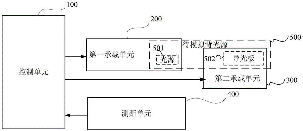
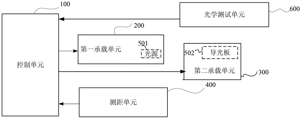
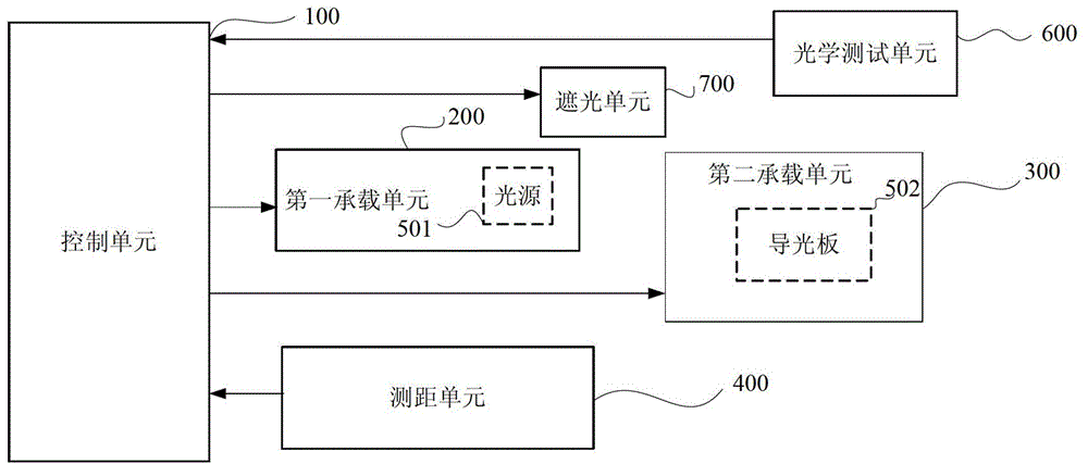
[0027] Such as figure 1 As shown, it is a structural block diagram of an embodiment of the present invention, and the optical simulation device of the backlight source of this embodiment includes:

[0028] The first carrying unit 200 and the second carrying unit 300, the first carrying unit 200 is used to place the light source 501 of the backlight source 500 to be simulated, and the second carrying unit 300 is used to place the light guide plate 502 of the backlight source 500 to be simulated ;

[0029] A distance measuring unit 400, configured to acquire the distance between the light source and the light guide plate;

[0030] The control unit 100 is connected with the first bearing unit and the second bearing unit, and is used for controlling the re...


PUM


Abstract

The invention provides an optical simulation device of a backlight source. The optical simulation device comprises a first bearing unit, a second bearing unit, a distance measurement unit and a control unit. The first bearing unit is used for placing a light source, and the second bearing unit is used for placing a light guide plate. The distance measurement unit is used for obtaining a distance between the light source and the light guide plate. The control unit is connected with the first bearing unit and the second bearing unit and used for controlling relative position between the first bearing unit and the second bearing unit. The optical simulation device of the backlight source adjusts the distance between the light source of the backlight source to be simulated and the light guide plate by controlling the first bearing unit and the second bearing unit, obtains the distance between the light source at the corresponding position and the light guide plate through the distance measurement unit, can actually simulate the optical effect of backlight source products, accordingly can perform actual optical simulation before the products are manufactured, and performs actual verification to the actually simulated backlight source to be developed.

Description

technical field [0001] The invention relates to the technical field of displays, in particular to an optical simulation device of a backlight source. Background technique [0002] The LCD display itself does not emit light. In order to clearly see the content displayed on the LCD display, it needs the support of the backlight to obtain color rendering. The backlight is generally composed of necessary optical components such as a light source, a diaphragm, a reflector, a light guide plate, and a back plate. [0003] The development and design of the existing backlight source is first simulated by optical simulation software, and key parameters such as the number of LEDs and the distance from the light guide plate are set, calculated from the design software, and then produced through the development of molds, but the results of simulation design calculations are often simulated. Deviations from the results in actual samples will affect the optical effect of the backlight, an...

Claims


Application Information

Patent Timeline
Patent Type & Authority Patents(China)
IPC IPC(8): G01M11/02F21V19/00F21V17/00G06F17/50
CPCY02T10/82
Inventor 刘淼马青雷嗣军周昊张伟张志丹李友池海朱红丽
Owner BOE TECH GRP CO LTD
Why Eureka
Try Eureka