Holographic 3D realization device and method

A realization method, 3D technology, applied in holographic process, optical recording/reproducing/erasing method, hologram recording material, etc., can solve the problem of loss of light wave phase information, etc., and achieve the effect of fast and convenient recording and display

Active Publication Date: 2016-08-24
BOE TECH GRP CO LTD +1
View PDF7 Cites 0 Cited by
  • Summary
  • Abstract
  • Description
  • Claims
  • Application Information

AI Technical Summary

Problems solved by technology

Ordinary photography only records the intensity (ie amplitude) information of the light wave and loses the phase information of the light wave

Method used


Image

  • Holographic 3D realization device and method
  • Holographic 3D realization device and method
  • Holographic 3D realization device and method

Examples


Embodiment 1

[0052] This embodiment describes a holographic 3D recording device, including:

[0053] Laser generating unit, beam splitting unit, photorefractive crystal and rotating unit,

[0054] The laser generating unit is used to emit laser light;

[0055] The beam splitting unit is configured to receive the laser light emitted by the laser generating unit and split the laser light to form reference light and object light directed to the subject;

[0056] The photorefractive crystal is used to respectively receive the reference light from the beam splitting unit and the object light diffusely reflected by the subject to form a holographic 3D image;

[0057] The rotation unit is configured to rotate the photorefractive crystal synchronously every time a new holographic 3D image is recorded.

[0058] In this embodiment, the recording of multiple holographic 3D images can be realized by rotating the photorefractive crystal in the holographic 3D recording device, and the recording is fas...

Embodiment 2

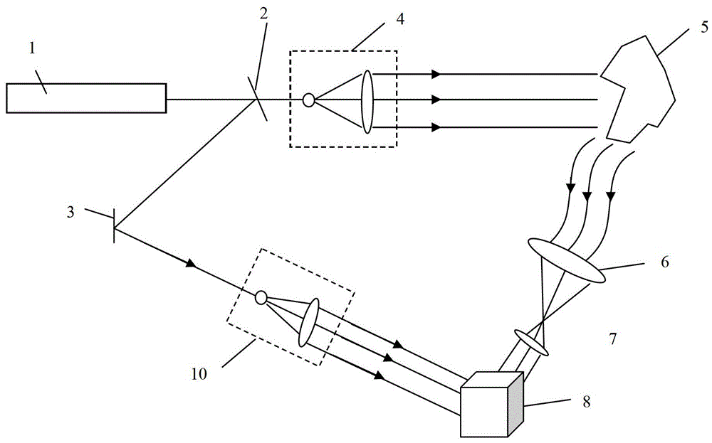
[0060] figure 1 Shown is a schematic structural diagram of a holographic 3D recording device described in this embodiment. Such as figure 1 As shown, in this embodiment, the device includes:

[0061] A laser generating unit 1, configured to emit laser light. In this embodiment, the laser light is a highly coherent monochromatic laser light;

[0062] The beam splitting unit 2 is configured to receive the laser light emitted by the laser generating unit 1 and split the laser light to form a reference light and an object light directed to the subject 5; in this embodiment, the beam splitting unit 2 is a semi-reflective and semi-transparent beam splitter, which has a beam splitting effect on the incident laser. According to a certain beam splitting ratio (such as 1:1, etc.), the incident beam is divided into a reflected beam and a transmitted beam at a certain angle. In the embodiment, the reflected light beam is used as the reference light, and the transmitted light beam is used...

Embodiment 3

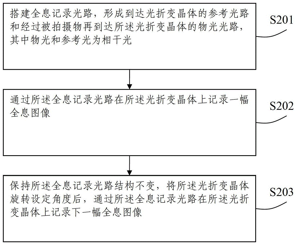
[0073] figure 2 The above is a flowchart of a holographic 3D recording method described in this embodiment, and the method includes:

[0074] S201 Build a holographic recording optical path to form a reference optical path reaching the photorefractive crystal and an object light path passing through the subject and then reaching the photorefractive crystal, wherein the object light and the reference light are coherent light;

[0075] S202 Record a holographic image on the photorefractive crystal through the holographic recording optical path;

[0076] S203 Keeping the structure of the holographic recording optical path unchanged, after rotating the photorefractive crystal to set an angle, record a holographic image on the photorefractive crystal through the holographic recording optical path.

[0077] In this embodiment, it can be set that the photorefractive crystal rotates synchronously every time the subject changes the subject angle, and a set of stereoscopic images repr...


PUM


Abstract

Devices and methods for recording and reproducing a holographic 3D image are provided. The devices for recording the holographic 3D image comprising: a laser generation unit for emitting a laser beam; a beam splitter unit configured to receive the laser beam from the laser generation unit and split the laser beam into a reference beam and an object beam directed to an object to be photographed; a photorefractive crystal configured to receive the reference beam from the beam splitter and the object beam diffused from the object to form a holographic 3D image; and a rotation unit configured to rotate the photorefractive crystal once every time one holographic 3D image is recorded. The holographic 3D image can be recorded and reproduced by the rotate the photorefractive crystal in light paths of recording and reproduction light beams, respectively.

Description

technical field [0001] The present invention relates to the field of display technology, in particular to a holographic 3D realization device and method. Background technique [0002] In linear optical materials (such as lenses, prisms, etc.), light beams just pass through each other without changing a certain property of the material itself. The photorefractive effect is the abbreviation of the photoinduced refractive index change effect. It does not refer to all changes in the refractive index induced by light, but specifically refers to the charge field formed by the photoconductive effect of the material under light radiation, and then the charge field is formed by the photoelectric effect. The effect that causes the refractive index to vary with the spatial distribution of light intensity. Since the optical properties of photorefractive materials can be changed by light passing through the material, such materials belong to nonlinear optical materials. Like the film p...

Claims


Application Information

Patent Timeline
Patent Type & Authority Patents(China)
IPC IPC(8): G03H1/12G03H1/22
CPCG03H1/265G03H1/02G03H1/04G03H1/041G03H2001/0268G03H2210/30G03H2223/17G03H2260/54G11B7/0065
Inventor 郑箫逸王俊伟崔晓鹏
Owner BOE TECH GRP CO LTD
Why Eureka
Try Eureka