In-wheel motor system

An in-wheel motor and wheel hub technology, which is applied in the field of in-wheel motor systems, can solve the problems of inefficient vehicle driving performance in space utilization, damage to in-wheel motors 40, etc., and achieves reduction of unsprung mass, The effect of increasing degrees of freedom and improving safety

Active Publication Date: 2013-04-24
HL MANDO CORP
View PDF4 Cites 17 Cited by
  • Summary
  • Abstract
  • Description
  • Claims
  • Application Information

AI Technical Summary

Problems solved by technology

[0006] In order to increase the torque of the in-wheel motor 40 in this in-wheel motor system, a speed reducer 30 needs to be provided. Since the braking system, that is, the disc 50 and the disc brake 60 need to be installed in the hub 10, the in-wheel When the motor system is coupled to the hub 10, there are inefficiencies in space utilization and problems with the rideability of the vehicle due to the unsprung mass
[0007] Particularly, when the in-wheel motor system is installed on the hub 10, although the disk 50, the disc brake 60 and the speed reducer 30 are located in the hub 10, due to the limited space in the hub 10, the in-wheel motor 40 will move towards the hub 10. , that is, protruding toward the interior of the vehicle, there is a problem of damage to the in-wheel motor 40 due to the impact of an external object

Method used


Image

  • In-wheel motor system
  • In-wheel motor system
  • In-wheel motor system

Examples


Embodiment Construction

[0049] Hereinafter, preferred embodiments of the present invention will be described in detail with reference to the accompanying drawings. First of all, the terms or words used in this specification and claims should not be interpreted by limiting the meaning in the dictionary, but should be based on the inventor's ability to use the terms in order to describe his invention in the best way. In principle, when a concept is defined properly, it interprets it as the meaning and concept of the technical idea of ​​this invention. Therefore, the embodiment described in this description and the structure shown in the accompanying drawings are only the most preferred embodiment of the present invention, and cannot fully represent the technical ideas of the present invention. Therefore, it should be understood that when applying for this application There may be various equivalents and modifications instead of them.

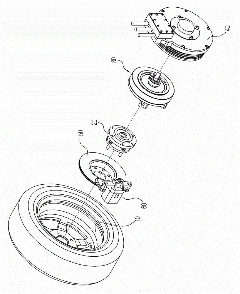
[0050] image 3 is an exploded perspective view showing an in-whe...


PUM


Abstract

An in-wheel motor system capable of maximizing the efficiency in using a wheel space by improving a mounting structure thereof, the in-wheel motor system installed at a wheel of a vehicle to transmit a rotational force including an axle installed at the wheel of the wheel and rotating together with the wheel, an in-wheel motor mounted inside the wheel and provided with a rotor and a stator that are used to generate a rotational force to drive the wheel, the rotor, and the stator disposed to face each other while having an accommodation space thereinbetween, a cycloid decelerator installed at a center of the in-wheel motor, and provided with an output shaft to transmit a rotational force at a reduced speed from the in-wheel motor to the axle and an input shaft that passes through the in-wheel motor and rotates together with the rotor, a disc installed at one end portion of the input shaft that protrudes by passing through the in-wheel motor, and a disc brake configured to provide a braking force by pressing the disc, wherein the in-wheel motor and the cycloid decelerator are disposed in a space formed inside the wheel.

Description

technical field [0001] The present invention relates to an in-wheel motor (in-wheel motor) system, and in more detail relates to an in-wheel motor system that improves the installation structure of the in-wheel motor system, so that the space of the wheel hub can be greatly and effectively utilized. Background technique [0002] In general, in-wheel motors, as a technology used in electric vehicles powered by electricity, are different from the way in which the power transmission through the engine-transmission-drive shaft in gasoline or diesel vehicles rotates and drives the wheels. The motor inside the rim is a device that transmits power directly to the hub. [0003] When such an in-wheel motor is applied, the driving and power transmission devices such as the engine, transmission or differential gear can be omitted, which not only reduces the weight of the vehicle, but also improves the independent control and driving performance of the wheels and reduces the friction in...

Claims


Application Information

Patent Timeline
Patent Type & Authority Applications(China)
IPC IPC(8): H02K7/00H02K7/10H02K7/08
CPCB60K2007/0092H02K7/08B60K7/00B60K2007/0038B60K7/0007H02K7/102H02K7/10B60K17/046Y02T10/641H02K7/00H02K7/116B60L7/24B60L2220/44B60L2240/421B60L2220/50Y02T10/64
Inventor 李忠星
Owner HL MANDO CORP
Why Eureka
Try Eureka