Low-frequency ultra-thin telephone receiver
A receiver, ultra-thin technology, applied in the field of receivers, can solve the problem that the thickness cannot be installed with mobile phones, etc., to achieve the effects of thickness reduction, enhanced low-frequency output, and increased air volume
- Summary
- Abstract
- Description
- Claims
- Application Information
AI Technical Summary
Problems solved by technology
Method used
Image
Examples
Embodiment 1
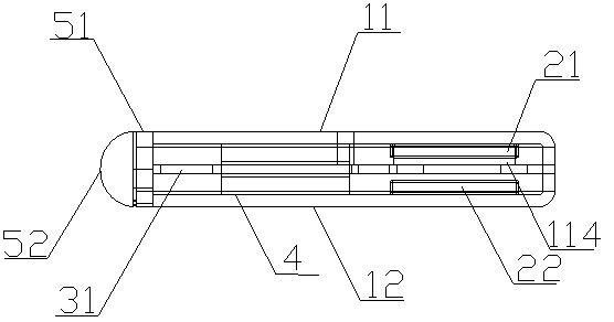
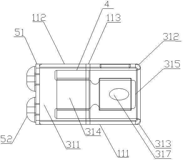
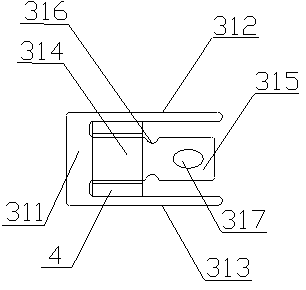
[0032] like Figure 1-6 As shown, the low-frequency ultra-thin receiver in this embodiment includes a housing 1, a driving mechanism, and a circuit board 51. The driving mechanism includes: an armature portion 31, which is E-shaped and flat-shaped, and the armature portion 31 includes an integral Formed base 311, two side wings and a middle part, the two side wings are a first side wing 312 and a second side wing 313, the middle part includes a root 314 on the base 311, and the root 314 extends forward to form The diaphragm part 315 and the armature part 31 can be made of soft magnetic alloy, and a through hole 317 is also provided on the diaphragm part 315, which can allow air to flow in and out of the inner cavity of the receiver, increasing the inner cavity The amount of air to enhance the effect of low-frequency output, the number of through holes 317 can also be opened as more than one according to the process requirements; the coil part 4 is sleeved on the root part 314 ...
Embodiment 2
[0047] Others are the same as those described in Embodiment 1, except that the above-mentioned through hole 317 may also be covered with a damping net, which can eliminate possible howling.
[0048] The working principle of the present invention is introduced below:
[0049] Both the original diaphragm and the armature part are combined into the current armature part 31, the armature part 31 is a flat plate, the root part 314 of the middle part is used for winding the coil 4 in the gap, and the part extending forward of the root part 314 is used as Replace the diaphragm part 315 of the existing diaphragm, so that the space occupied by the original diaphragm is firstly compressed; the original shell and the iron core for installing the magnet are combined into the current shell 1, and the shell 1 is divided into upper and lower parts. The upper casing 11 and the lower casing 12, the first magnet 21 and the second magnet 22 are relatively installed on the inner walls of the uppe...
PUM
 Abstract
Description
Claims
Application Information
 - R&D
- Intellectual Property
- Life Sciences
- Materials
- Tech Scout
- Unparalleled Data Quality
- Higher Quality Content
- 60% Fewer Hallucinations
Browse by: Latest US Patents, China's latest patents, Technical Efficacy Thesaurus, Application Domain, Technology Topic, Popular Technical Reports.
© 2025 PatSnap. All rights reserved.Legal|Privacy policy|Modern Slavery Act Transparency Statement|Sitemap|About US| Contact US: help@patsnap.com


