
Vehicle wheel

A wheel and rim technology, applied in the direction of wheels, spoked wheels, wheel cover discs, etc., can solve the problem of short stroke, insufficient adjustment force, not allowed to be used in the radial direction caused by centrifugal force to move from the inner open position to Issues such as covers in the outer closed position to achieve good thermal contact

Inactive Publication Date: 2013-04-24
AUDI AG
View PDF6 Cites 9 Cited by
  • Summary
  • Abstract
  • Description
  • Claims
  • Application Information

AI Technical Summary

Problems solved by technology

Furthermore, with known thermally controlled adjusting elements, sometimes based on thermobimetallic materials or shape-memory alloys, only relatively short strokes and possibly insufficient adjusting forces can be produced, such adjusting elements are not permitted to be used, for example, with Centrifugal force-induced radial movement of the cover from the inner open position to the outer closed position in the wheel, because considerable forces have to be generated in this wheel design in order to achieve a given wheel rotation and existing centrifugal force can also squeeze the cover into the open position

Method used


Image

  • Vehicle wheel
  • Vehicle wheel
  • Vehicle wheel

Examples


Embodiment Construction

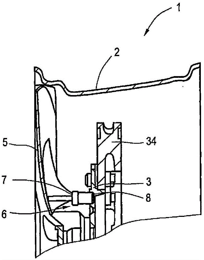
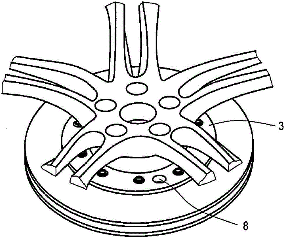
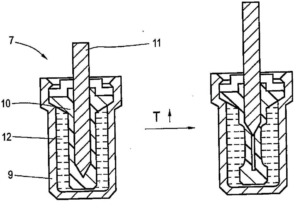
[0038] figure 1 A wheel 1 according to the invention is shown, comprising a rim 2 , a brake disc drum 3 fastened to the rim and a brake disc 34 fastened to the brake disc drum. See for example the following Figure 4 The rim 2 has various perforations 4 , for which a plate-shaped cover 5 is respectively assigned, by means of which the perforations can be closed or opened. The individual covers 5 are mounted pivotally movable on the rim 2 via pivot axes, which will be discussed later. In order to be able to deflect the cover into the open position due to the thermal conditions on the brake disc 34 for ventilation via the perforations 4 on the rim side, a thermally controlled element in the form of an expanding material work element 7 is provided in the wheel according to the invention. An adjustment element 6 is arranged on the brake disk fastening drum 3 and is thus thermally coupled to the brake disk 34 . Because the brake disc is directly arranged on the brake disc fixed ...


PUM


Abstract

A vehicle wheel (1) comprising a wheel rim (2), a brake pot (3) fastened thereto and a brake disk (34) fastened to the brake pot, wherein on the wheel rim there are provided a plurality of pivotably mounted, preferably plate-shaped covering elements (5) for temporarily closing off associated apertures (4) in the wheel rim, which covering elements can be moved from a closed position into an open position by means of at least one thermally controlled setting element (6), wherein the setting element (6) is an expansion material working element (7) which is thermally coupled to the brake disk (34) so as to permit a transfer of heat from the brake disk (34) to the expansion material working element (7).

Description

technical field [0001] The invention relates to a wheel comprising a rim, a brake disc holding drum (Bremstopf) fixed to the rim and a brake disc fixed to the brake disc holding drum, wherein a plurality of rotatable bearings are arranged on the rim There are provided, preferably plate-shaped coverings for temporarily closing the corresponding rim-side perforations which can be moved from the closed position into the open position by means of at least one thermally controlled adjusting part. Background technique [0002] The design of modern rims is determined by different, partially conflicting requirements. In addition to achieving a simple rim profile that can be produced easily, there is also a central requirement that the rim achieve the highest possible air flow in order to be able to cool the brake disc optimally by the air flow during the braking situation. Furthermore, when the brake discs are rear heated when parked, it must be ensured that the heat is transferred...

Claims


Application Information

Patent Timeline
Patent Type & Authority Applications(China)
IPC IPC(8): B60B3/10B60B7/00B60B19/10F16D65/847
CPCB60B2900/321B60B7/0073B60B19/10B60B7/04F16D2065/783B60B7/06B60B7/002F16D65/847B60B2900/513B60B7/0086
Inventor 卡尔-海因茨·梅汀格克里斯托夫·科西拉沃尔夫冈·施密德
Owner AUDI AG
Learn More