Eureka AIR delivers breakthrough ideas for toughest innovation challenges, trusted by R&D personnel around the world.

Liquid flow path control device for drive device for vehicle

A liquid flow path and drive device technology, applied in the field of liquid flow path control devices, can solve problems such as lubrication and cooling

Inactive Publication Date: 2013-04-24
HONDA MOTOR CO LTD
View PDF7 Cites 7 Cited by
  • Summary
  • Abstract
  • Description
  • Claims
  • Application Information

AI Technical Summary

Problems solved by technology

[0011] However, in the hydraulic control device 120 described in Patent Document 1, after the electric hydraulic pump 121 is activated, the spool 122a does not move in the discharge direction until hydraulic pressure of a predetermined pressure is input to the oil chamber 122c of the regulator valve 122 and does not move. Supplying oil to the oil supply part 130 may cause insufficient lubrication and cooling
[0012] In addition, when high-pressure oil is supplied to the hydraulic clutch 107, if the oil is supplied to the oil chamber 122d, the spool 122a moves in the non-drainage direction and the oil is not supplied to the oil supply part 130, and insufficient lubrication and cooling may occur.

Method used


Image

  • Liquid flow path control device for drive device for vehicle
  • Liquid flow path control device for drive device for vehicle
  • Liquid flow path control device for drive device for vehicle

Examples


no. 2 approach

[0204] Next, refer to Figure 22 , the second embodiment of the present invention will be described. It should be noted that the second to sixth embodiments to be described later are embodiments in which the configuration of the hydraulic circuit of the first embodiment is partially changed, and the same members are denoted by the same reference numerals and description thereof will be omitted.

[0205] The hydraulic circuit 71A of the second embodiment is different from the hydraulic circuit 71 of the first embodiment in that the overflow drain pipe 86 of the relief valve 84 is not connected to the oil bottom where the oil suction port 70a of the electric hydraulic pump 70 is arranged. The shell 80 is connected to the reservoir 79 disposed at a position higher than the oil pan 80 in the vertical direction. In addition, the oil reservoir side end portion 86 a of the overflow drain pipe 86 is arranged at a position higher than the vertically uppermost portion of the reservoir ...

no. 3 approach

[0208] Next, refer to Figure 23 , the third embodiment of the present invention will be described.

[0209] The hydraulic circuit 71B of the third embodiment is different from the hydraulic circuit 71 of the first embodiment in that the brake oil circuit switching valve 74 of the first embodiment is not provided, and the brake oil circuit 77 is directly connected to the solenoid valve 83 The first radial hole 183 (refer to Figure 8 )connect.

[0210]In this hydraulic circuit 71B, by controlling the operation mode of the electric hydraulic pump 70 and the energization and de-energization of the electromagnetic element 174 in the same manner as the hydraulic circuit 71 of the first embodiment, it can be compared with the hydraulic circuit of the first embodiment. 71 similarly controls the hydraulic brakes 60A, 60B into the disengaged state, the weakly engaged state, and the engaged state, and can always lubricate and cool the lubricating and cooling unit 91 . It should be n...

no. 4 approach

[0212] Next, refer to Figure 24 , the fourth embodiment of the present invention will be described.

[0213] The hydraulic circuit 71C of the fourth embodiment is different from the hydraulic circuit 71 of the first embodiment in that the solenoid valve 83 of the first embodiment is not provided, and the oil chamber 74c of the brake oil circuit switching valve 74 is directly connected to the hydraulic circuit 71 of the first embodiment. The second line oil passage 75b of the line oil passage 75 is connected.

[0214] In this hydraulic circuit 71C, the electrohydraulic pump 70 can operate in three modes, namely, an extremely low pressure mode in addition to the high pressure mode and the low pressure mode, and the force of the spring 73b of the oil circuit switching valve 73 is set as follows: When the electric hydraulic pump 70 operates in the low pressure mode and the extremely low pressure mode, under the action of the hydraulic pressure of the pipeline oil passage 75 inpu...


PUM


Abstract

A liquid flow path control device is provided with: a liquid supply device for supplying liquid to a hydraulic connection and disconnection means and a section to which the liquid to be supplied; and a flow path changeover valve either disposed in a liquid flow path for connecting the liquid supply device and the section to which the liquid is to be supplied or disposed so as to bridge between the liquid flow path and a liquid pressure path which connects the liquid supply device and the hydraulic connection and disconnection means. The flow path changeover valve is provided with: a valve element capable of being switched between a first operation position and a second operation position; a restoration means for pressing the valve element from the second operation position in the direction toward the first operation position; and a liquid chamber for storing the liquid for pressing the valve element from the first operation position in the direction toward the second operation position. The liquid chamber is connected to the liquid supply device when the valve element is located at the first and second operation positions. The liquid flow path has different flow path resistance when the valve element is at the first operation position and when the valve element is at the second operation position.

Description

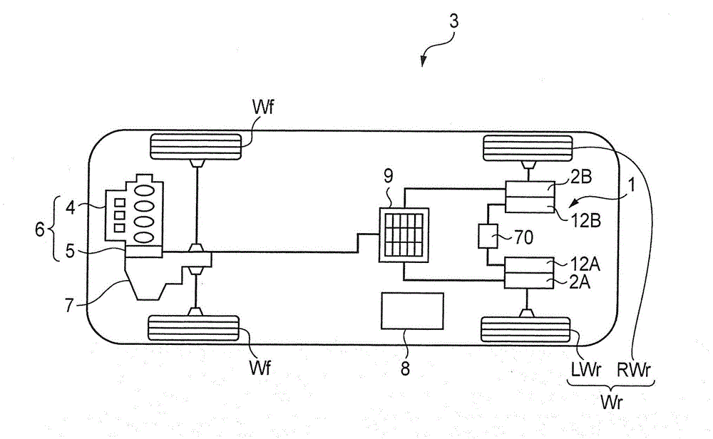
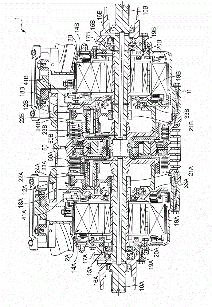
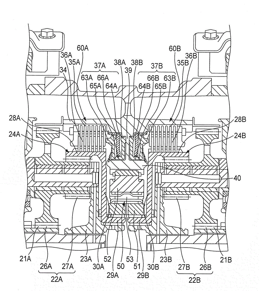
technical field [0001] The present invention relates to a liquid flow path control device for a vehicle driving device, which includes an electric motor generating driving force of the vehicle, and a hydraulic disconnecting and connecting mechanism provided on a power transmission path between the electric motor and wheels to disconnect or connect the power. Background technique [0002] As such a fluid channel control device for a vehicle drive device, a hydraulic control device for a vehicle drive device described in Patent Document 1 is conventionally known. Such as Figure 32 As shown, the hydraulic control device 120 of the vehicle driving device can supply the oil discharged from the electric hydraulic pump 121 to the hydraulic clutch 107 through the regulator valve 122, the check valve 123 and the clutch oil passage switching valve 124, and An accumulator 126 is connected to an oil supply passage 125 connecting the check valve 123 and the clutch oil passage switching ...

Claims


Application Information

Patent Timeline
IPC IPC(8): F16H57/04B60K6/387B60K6/442B60K6/52B60L11/14B60L50/16
CPCY02T10/6217F16H57/0476B60L7/26B60K6/387Y02T10/7005Y02T90/16B60L2240/421B60K17/046F16H61/0021B60L2240/36B60K7/0007Y02T10/705F16H57/0434Y02T10/6265B60K1/00B60L2240/423B60L3/0023B60L1/003B60L2240/12B60L15/2036B60L2240/486B60L15/2009B60L11/1877F15B13/02B60K6/46B60L2260/28B60L11/14B60K6/52Y02T10/7077F16H57/0446Y02T10/642F16H2061/0037B60L2220/46B60K2007/0046B60K2007/0092B60Y2400/427B60L50/16B60L50/66Y02T10/62Y02T10/64Y02T10/70Y02T10/7072Y02T10/72
Inventor 星野谷武中山茂
Owner HONDA MOTOR CO LTD
Why Eureka
Eureka Blog
Learn More