
Discharging device

The technology of feeding and leveling device is applied in the field of automatic cleaning device for feed trough, which can solve the problems of moldy feed, failure of feeding device and failure to return normally.

Inactive Publication Date: 2013-05-01
广州市翔顺畜牧设备有限公司
View PDF11 Cites 9 Cited by
  • Summary
  • Abstract
  • Description
  • Claims
  • Application Information

AI Technical Summary

Problems solved by technology

If the feed on the head and tail of the feed trough is not completely scraped clean by the feed return device, the feed return device will move to the edge of the feed trough driven by the feeder, and the unscraped feed will go to the edge of the feed trough. Push, when it accumulates to a certain extent, it will be spilled outside the trough to cause waste, and it will form a dead angle and cause the feed to become moldy; if there are more feed at the head and tail of the feed trough, it is easy to interfere with the cooperation of the return device and the leveling device; When the barb of the unloading device is not properly hooked into the square hole of the feeder, it will cause the unloading device to be pushed to the edge of the trough, and cannot return normally, and the unloading device will lose its function; Under the action of the external stopper, occasionally it cannot be separated from the leveler normally, and the material return device will move along with the leveler all the way, and there will be serious accidents such as full material seepage and damage to the cage equipment

Method used


Image

  • Discharging device
  • Discharging device
  • Discharging device

Examples


Embodiment Construction

[0022] The present invention will be described in further detail below in combination with specific embodiments.

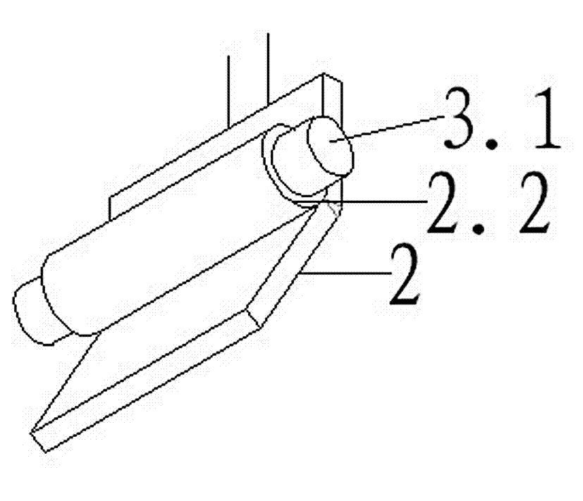
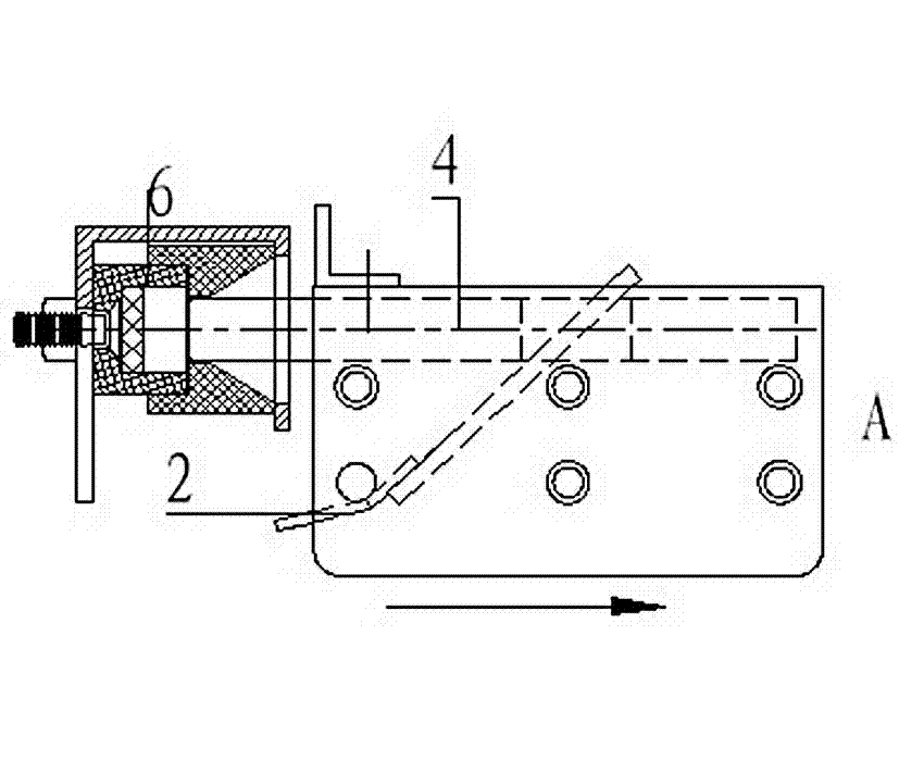
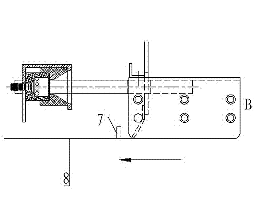
[0023] Such as figure 1 , figure 2 and image 3 The shown material return device includes two brackets 1 and six connecting rods connecting the two brackets 1 , and the connecting rods are connected to the brackets 1 by screws. The stripping scraper 2 is connected to the connecting rod 3.1, which is the rotation fulcrum of the stripping scraper 2, such as figure 2 As shown, the connecting ring 2.2 on the scraper 2 is sleeved on the connecting rod 3.1. The guide rod 2.1 of the stripping scraper 2 is installed in the guide hole 4.1 of the push rod 4, and the push rod 4 is installed on the first row of connecting rods. There is a limit block 5 on the front end of the bracket 1, and the limit block 5 and the connecting rod 3.2 jointly limit the rotation range of the stripping scraper.

[0024] Such as Figure 5 and Figure 6 As shown, the push rod 4 is connec...


PUM


Abstract

The invention discloses a discharging device, which comprises a support and a discharging scraper rotating around an upper pivot of the support. When the discharging scraper rotates to contact the bottom of a trough, the discharging device moves from the end part of the trough to the middle for discharging; and when the discharging scraper rotates to leave the bottom of the trough, the discharging device retreats to the end part of the trough and cannot push a residual feed at the bottom of the trough back to the end part of the trough. The discharging device can automatically clean two ends of the trough thoroughly without leaving dead angles, and is connected with a feed levelling device through a magnet, so that the discharging device and the feed levelling device are connected and separated more reliably, and the safety is higher.

Description

【Technical field】 [0001] The invention relates to an automatic cleaning device for a feed trough. 【Background technique】 [0002] In the animal husbandry industry, automatic feeders are generally used to add feed to the feed trough, and the head and tail ends of the feed trough have accumulated a large amount of feed because there is no poultry eating, which requires cleaning. [0003] There are two commonly used devices for cleaning the accumulated material at the head and tail ends of the feed trough: [0004] A device: Open holes at the bottom of the head and tail of the feed trough and install the return barrel, the return barrel leads to the lower feed trough, and the return barrel of the bottom feed trough leads to the receiving basin. When the flat feeder pushes forward the remaining feed on the head and tail of the feed trough, the feed will be conveyed to the lower feed trough through the feeding cylinder, and finally conveyed to the bottom receiving basin by the f...

Claims


Application Information

Patent Timeline
IPC IPC(8): A01K5/02A01K39/012
Inventor 赖梁箫
Owner 广州市翔顺畜牧设备有限公司
Learn More