
Magnetic separation device and method

A magnetic separation device and magnetic pole technology, applied in the fields of magnetic separation, small magnetic separation devices, and magnetic separation devices, can solve problems such as difficulty in mastering, poor precision and accuracy, achieve high precision and accuracy, and avoid analysis errors , the effect of avoiding the loss of magnetic particles

Inactive Publication Date: 2013-05-01
王秋莲 +3
View PDF5 Cites 5 Cited by
  • Summary
  • Abstract
  • Description
  • Claims
  • Application Information

AI Technical Summary

Problems solved by technology

However, although this method is simple to operate, its precision and accuracy are poor. Sometimes the difference between the results of the same sample and the same analyst can be as high as 3%-4%, which is difficult to master.

Method used


Image

  • Magnetic separation device and method
  • Magnetic separation device and method
  • Magnetic separation device and method

Examples


Embodiment 1

[0041] Embodiment 1: magnetic separation device of the present invention

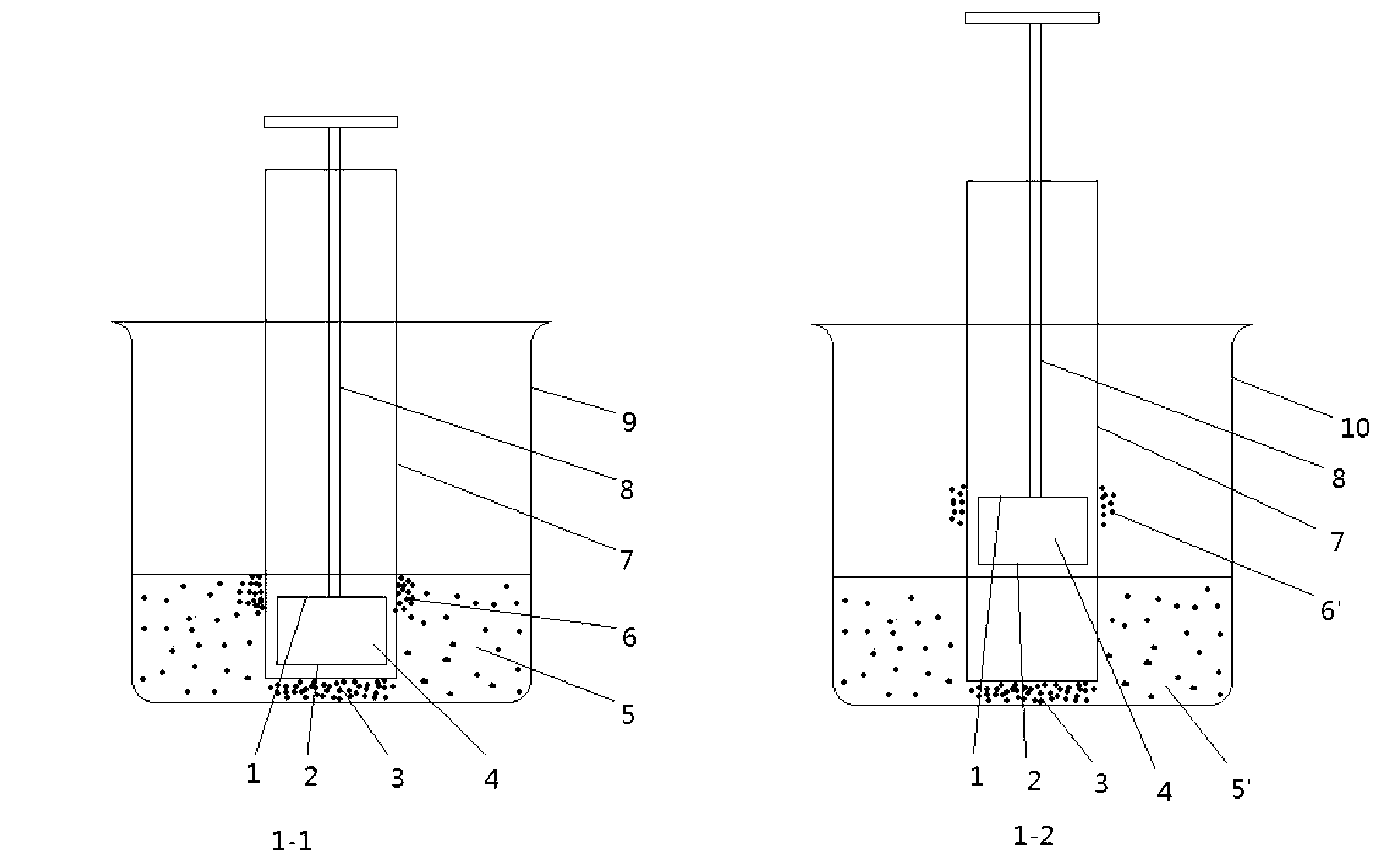
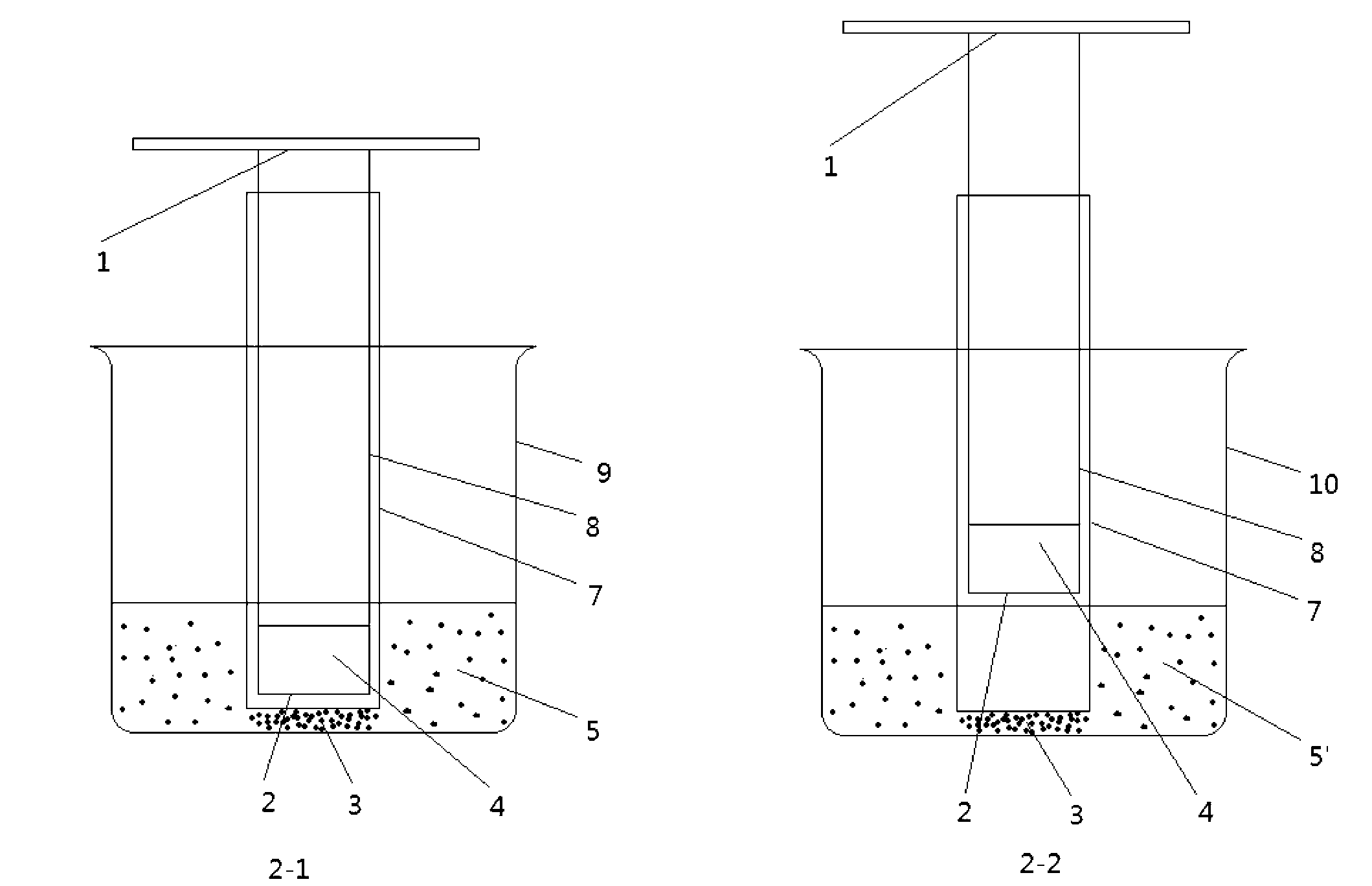
[0042] figure 2 is a schematic structural view of a magnetic separation device according to an embodiment of the present invention, wherein diagram 2-1 is a schematic diagram of the magnetic separation device when it adsorbs magnetic particles, Figure 2-2 It is a schematic diagram of the magnetic separation device releasing magnetic particles.

[0043] Such as diagram 2-1 The magnetic separation device of the present invention shown includes a combined magnet (composed of a permanent magnet (4) and a ferromagnetic body (8) that is substantially equal in diameter to the permanent magnet (4) through magnetic connection), and a non-magnetic a glass jacket (7), and a first container (9) for holding a mixture suspension (5) of magnetic and non-magnetic particles. One pole of the permanent magnet (4) is magnetically connected to one end of the ferromagnet (8), the other pole of the permanent magnet (4...

experiment example 1

[0045] Experimental example 1: Magnetic separation device of the present invention and the magnetic iron measuring method using this device

[0046] 1. Experimental part

[0047] 1. Magnetic separation device

[0048] use as figure 2 In the magnetic separation device shown, the permanent magnet (4) is a short cylindrical permanent magnet with a diameter of 1.5cm and a height of 0.8cm, and the measured magnetic field strength (outside the casing) is (900±100)×10 3 / 4π(A / m); the ferromagnet (8) is an iron pipe with a handle, the length of the iron pipe is 10cm, the outer diameter of the iron pipe is 1.3cm, the thickness of the iron pipe is 0.2cm, the length of the handle is 8.5cm, and the width is 1.4cm; the glass jacket ( 7) It is a flat-bottomed glass tube with a height of 9.5cm, an inner diameter of 1.7cm, and an outer diameter of 1.9cm; the first container and the second container are 50mL small flat-bottomed beakers with a diameter of 4.8cm, a height of 5.8cm, an outer d...


PUM


Abstract

The invention relates to a magnetic separation device, which comprises a magnetic body, a nonmagnetic sheath and a first container, wherein the magnetic body is provided with a first magnetic pole and a second magnetic pole, the nonmagnetic sheath is movably sheathed on the first magnetic pole, the first container is used for containing mixture suspension liquid of magnetic particles and nonmagnetic particles, and when the first magnetic pole sheathed with the nonmagnetic sheath is placed into the mixture suspension liquid for absorbing the magnetic particles, the second magnetic pole is positioned above the liquid level of the mixture suspension liquid. The magnetic separation device provided by the invention can be used for simply and fast realize the magnetic separation on the magnetic particles, and the magnetic particle loss caused by accidental magnetic particle bringing out by the magnetic body is effectively prevented. When a magnetic iron content measuring method of the magnetic separation device provided by the invention is adopted, the analysis error caused by magnetic particle bringing by the magnetic body can be avoided, and higher precision and higher accuracy are realized.

Description

technical field [0001] The invention belongs to the technical field of magnetic separation, and in particular relates to a magnetic separation device and a magnetic separation method using the magnetic separation device, wherein the magnetic separation device is a small-sized magnetic separation device suitable for analysis experiments. Background technique [0002] Magnetic separation is a beneficiation method that uses the magnetic difference between minerals to separate different minerals in an inhomogeneous magnetic field. After the ore to be selected enters the separation space of the magnetic separation equipment, it is affected by the combined action of magnetic force and mechanical force, and moves along different paths, and the ore pulp is intercepted separately to obtain different products. [0003] Magnetic analyzers such as magnetic separation tubes, magnetic analyzers, induction roller magnetic separators, and strong magnetic mineral separators are commonly used...

Claims


Application Information

Patent Timeline
Patent Type & Authority Applications(China)
IPC IPC(8): B03C1/32
Inventor 王秋莲姚永生张德录代建强
Owner 王秋莲
Learn More