Diode lead-out line straightening machine

A technology for diodes and lead wires, applied in the field of diode lead wire straightening machines, which can solve problems such as damaged tin plating, low production efficiency, complex mechanism, etc., and achieve the goals of reducing labor costs, improving production efficiency, and expanding the scope of use Effect

Inactive Publication Date: 2013-05-01
张成骏
View PDF7 Cites 9 Cited by
  • Summary
  • Abstract
  • Description
  • Claims
  • Application Information

AI Technical Summary

Problems solved by technology

Most of the current diodes are aligned manually. Due to labor-intensive, low production efficiency, frequent personnel flow and other reasons, the alignment of diodes has become the production bottleneck of various manufacturers.
Many domestic counterparts have seen this bottleneck. Some manufacturers have tried to replace the manual straightening method with machine straightening methods, and have made useful attempts. These methods use vibrating material trays to arrange the direction, and use the gap between the transmission belts to form a straightening channel. Alignment in the vertical and horizontal directions replaces manual alignment to some extent, but due to the characteristics of mechanical alignment, the diodes rub against each other during the alignment process, the tin plating layer is damaged and blackened, and two-way forced straightening, This caused the breakage and jamming of the diode leads. At the same time, the mechanism was complex, the noise was high, and the diodes with large bends could not be separated automatically. The follow-up had to be manually selected, which caused new confusion for diode manufacturers.

Method used


Image

  • Diode lead-out line straightening machine
  • Diode lead-out line straightening machine
  • Diode lead-out line straightening machine

Examples


Embodiment Construction

[0046] In order to make the content of the present invention easier to understand clearly, the present invention will be described in further detail below according to specific embodiments in conjunction with the accompanying drawings,

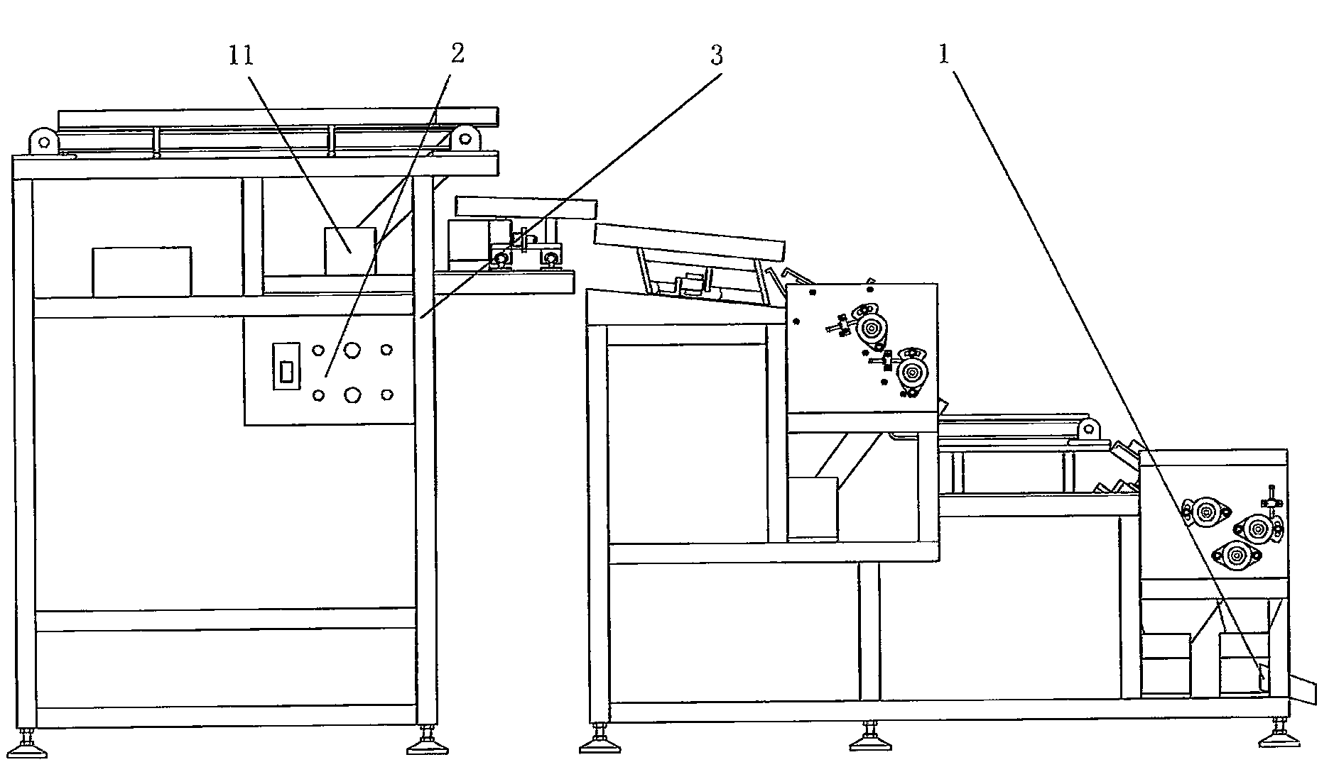
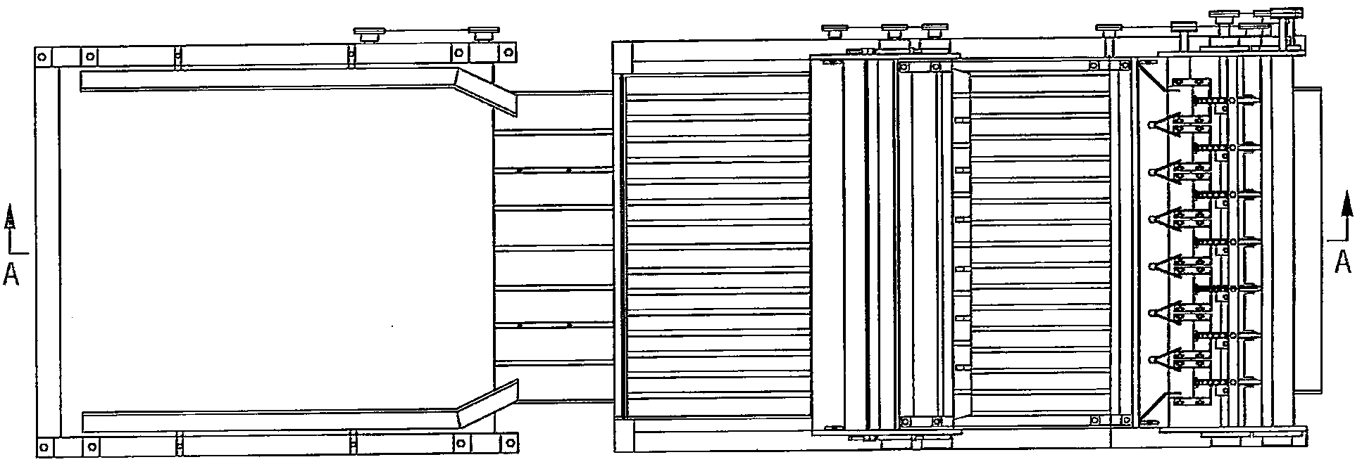
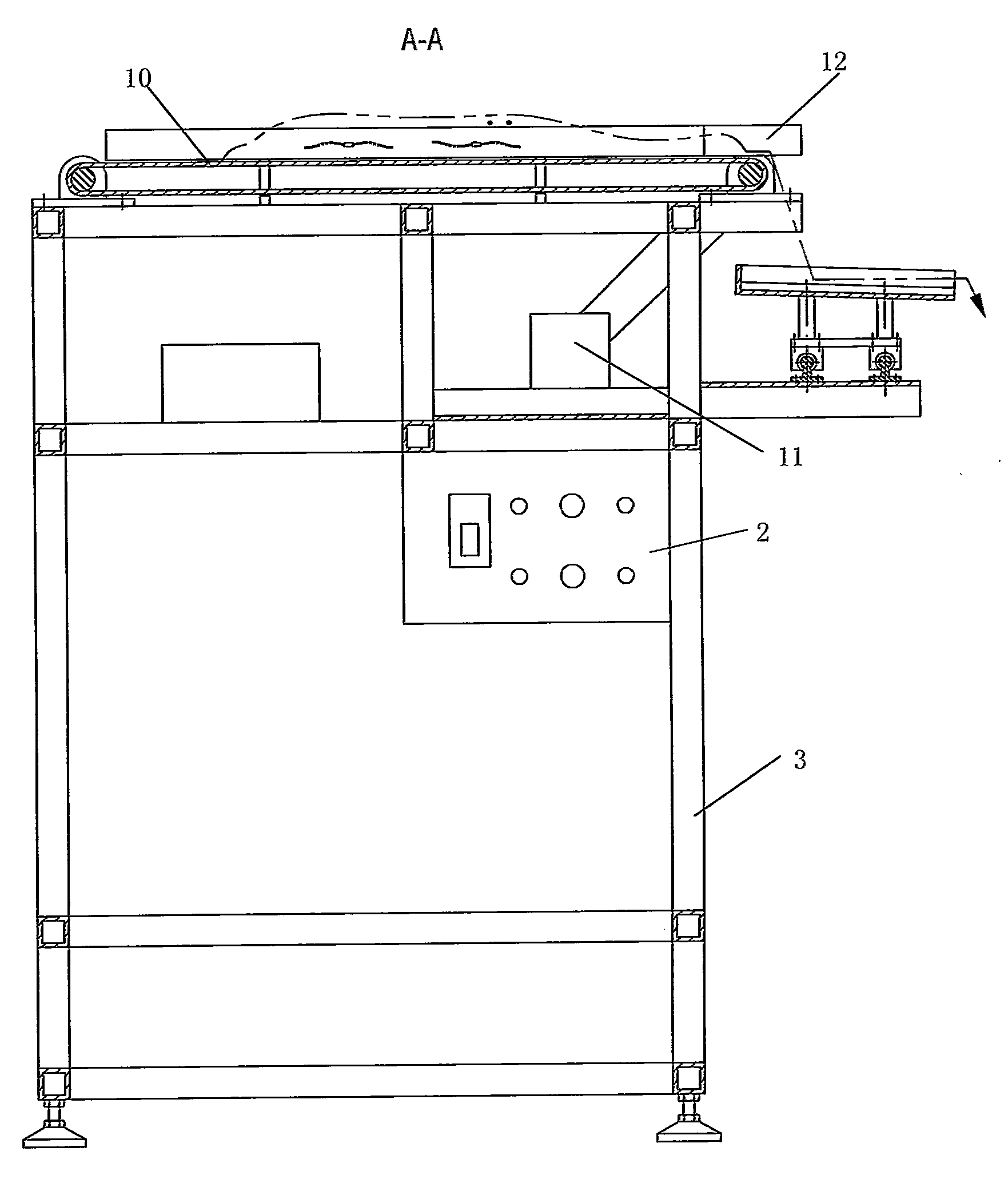
[0047] Such as Figure 1~22 As shown, a diode lead wire straightening machine, it includes the initial straightening device, the transmission device 60, the oscillating row to the fine straightening device, the finished product collecting bucket 1, the control system 2, the frame 3 and the diodes are spaced and Feeder arranged in sequence. The feeding device, the primary straightening device, the transmission conveying device 60, and the oscillating row to the fine straightening device are successively connected. The material baffle plate 4, the rubbing material bottom plate 5 and the initial straightening roller 6, the blanking baffle plate 4 and the rubbing material bottom plate 5 are all fixedly connected on the frame 3, and the lower end ...


PUM


Abstract

The invention discloses a diode lead-out line straightening machine, which comprises a primary straightening device, a transmission conveying device, an oscillation orientation precise straightening device, a finished product gathering hopper, a control system, a stander and a supply device enabling the diodes to be sequentially arranged at intervals. The supply device, the primary straightening device, the transmission conveying device and the oscillation orientation precise straightening device are sequentially connected with one another, the oscillation orientation precise straightening device comprises a first straightening roll, a second straightening roll, a material uniformly-distributing mechanism, a reversing device enabling the orientation of lead-out liens of the diodes to be in consistency, a second drive mechanism for driving the first straightening roll to rotate and supplying power to the material uniformly-distributing mechanism and a third drive mechanism for driving the second straightening roll to rotate, the first straightening roll and the second straightening roll make relative differential movement, and a precise straightening passage with an adjustable gap and capable of dropping the diodes processed by the material uniformly-distributing mechanism is arranged between the first straightening roll and the second straightening roll. Through twice screening, the twisting, broken pin and reject phenomenon of the diodes in the straightening process can be avoided, and the phenomenon that the diode misses the straightening also can be avoided.

Description

technical field [0001] The invention relates to a diode lead wire straightening machine, which belongs to special equipment for processing diode lead wire straightening. Background technique [0002] At present, my country is a big country in the production of diodes. There are hundreds of companies producing diodes in the country. The annual production of diodes is about 120 billion diodes. However, the lead wires of unplated red capillary tubes are bent after being electroplated, and they must be straightened before printing and testing packages. . Most of the current diodes are aligned manually. Due to labor-intensive, low production efficiency, frequent personnel flow and other reasons, the alignment of diodes has become the production bottleneck of various manufacturers. Many domestic counterparts have seen this bottleneck. Some manufacturers have tried to replace the manual straightening method with machine straightening methods, and have made useful attempts. These m...

Claims


Application Information

Patent Timeline
Patent Type & Authority Applications(China)
IPC IPC(8): B21F1/02H01L21/67
Inventor 张成骏
Owner 张成骏
Why Eureka
Try Eureka