Conveying method and device for conveying sand box set with temperature change through hydraulic cylinder

A technology of temperature change and hydraulic cylinder, which is applied in the field of sand box group, can solve problems such as difficult working speed, working distance, damage of casting equipment, failure to transport sand box to the specified position, etc., and achieve the effect of eliminating errors

Inactive Publication Date: 2013-05-01
SINTOKOGIO LTD
View PDF9 Cites 4 Cited by
  • Summary
  • Abstract
  • Description
  • Claims
  • Application Information

AI Technical Summary

Problems solved by technology

In Patent Document 1, a pneumatic cylinder is used to replace the hydraulic push cylinder and hydraulic buffer cylinder, but the pneumatic cylinder has the following problems: it is difficult to finely control the working speed, working distance, etc., and it cannot fully cope with the heavy sand box
[0005] That is, in the method of Patent Document 2, in the case of cooling the flask, a conveying shortage (feeding shortage) of about 175 mm at maximum occurs, and the flask cannot be conveyed to a predetermined position.
In addition, when the temperature of the flask is excessively raised due to the secondary cooling of the billet after the binning, the conveying equipment is stopped during operation, and the stop position of the flask exceeds a predetermined position, there is a possibility that the casting equipment may be damaged.

Method used


Image

  • Conveying method and device for conveying sand box set with temperature change through hydraulic cylinder
  • Conveying method and device for conveying sand box set with temperature change through hydraulic cylinder
  • Conveying method and device for conveying sand box set with temperature change through hydraulic cylinder

Examples


Embodiment Construction

[0021] Embodiments of the present invention will be described in detail below based on the drawings.

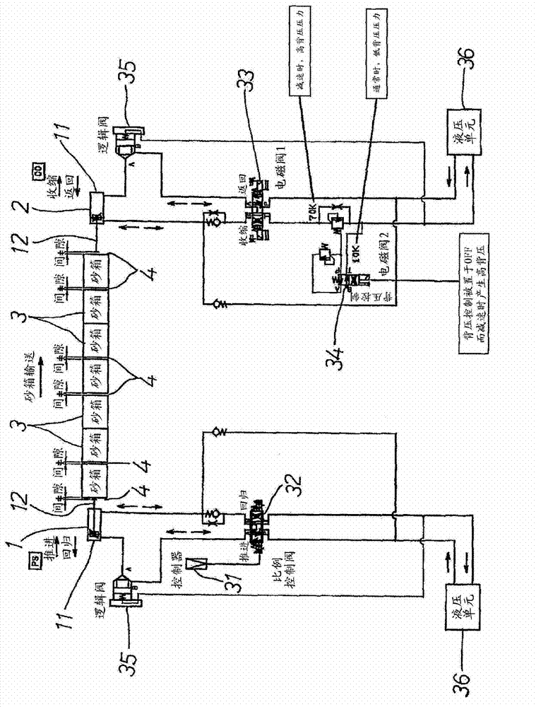
[0022] figure 1 A conveying line and a hydraulic piping system diagram showing a hydraulic push cylinder 1 and a hydraulic buffer cylinder 2 arranged opposite to each other to clamp the flask groups 3 and 3 and to convey intermittently a distance of one flask size at a time. There are various devices not shown in the figure between the hydraulic push cylinder 1 and the hydraulic buffer cylinder 2 , and gaps 4 , 4 are provided in front of each device and in front of the hydraulic push cylinder 1 and the hydraulic buffer cylinder 2 as shown in the figure. In addition, the hydraulic push cylinder 1 has a stroke substantially greater than the sum of these gaps 4 , 4 .

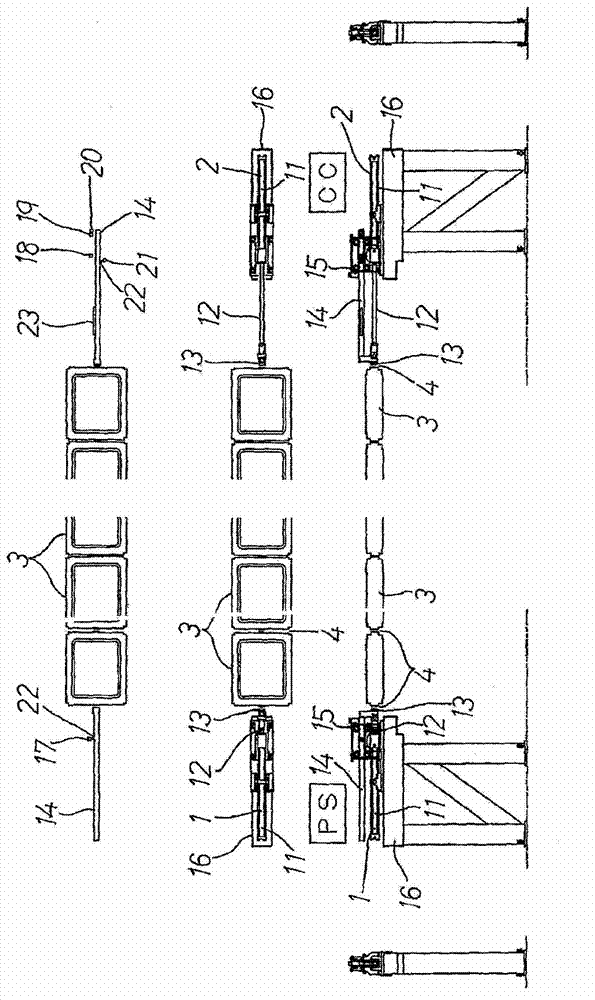
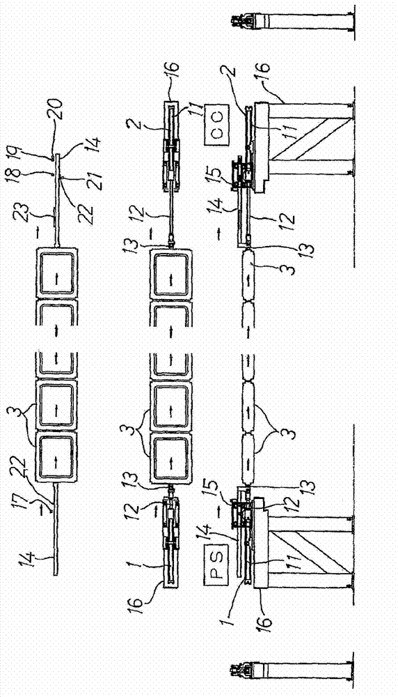
[0023] Such as Figure 2 ~ Figure 6 As shown, at the ends of the piston rods 12, 12 of the hydraulic push cylinder 1 and the hydraulic buffer cylinder 2, sand box push heads 13, 13 are installed, and guide rolle...


PUM


Abstract

The present invention provides a conveying method and a device for conveying a sand box set without sand box stop position error when large thermal expansion amount of the sand box exists. The conveying method provided by the invention comprises the following steps: sand box gathering step in which a hydraulic push cylinder (1) operates for pushing the sand box set (3) which is configured in series to a hydraulic buffer cylinder (2) and eliminating a clearance (4); a conveying step in which the hydraulic push cylinder (1) operates in high speed and the hydraulic buffer cylinder (2) is switched to a high-back-pressure state for reducing speed in a speed reduction area, thereby conveying the sand box set (3) for a distance which is equivalent with the size of one sand box; and a final step for further retreating the hydraulic buffer cylinder (2) after the sand box set (3) is stopped, thereby forming a clearance (4) between the hydraulic buffer cylinder (2) and the sand box set (3).

Description

technical field [0001] The invention relates to a hydraulic push cylinder and a hydraulic buffer cylinder to clamp a sand box group with a large temperature change such as a casting sand box, and transport it at a distance (pitch) of the size of a sand box each time. Method and device for intermittent delivery. Background technique [0002] As shown in Patent Document 1, a technology has been known for a long time that uses hydraulic push cylinders and hydraulic buffer cylinders to clamp sand box groups arranged in series, and transports sand boxes one at a time with no gap between them. Intermittent conveying in the form of a box-sized distance. In Patent Document 1, a pneumatic cylinder is used to replace the hydraulic push cylinder and the hydraulic buffer cylinder, but the pneumatic cylinder has the following problems: it is difficult to finely control the working speed, working distance, etc., and it cannot fully cope with the heavy sand box. [0003] Therefore, the p...

Claims


Application Information

Patent Timeline
Patent Type & Authority Applications(China)
IPC IPC(8): B22C25/00
Inventor 大野泰嗣
Owner SINTOKOGIO LTD
Why Eureka
Try Eureka