
Drain Pipe Elbow Mold

A drainage pipe and mold technology, which is applied in the field of injection mold manufacturing, can solve problems such as injury to operators and easy damage, and achieve the effects of convenient maintenance, improved strength, and reduced flash.

Active Publication Date: 2015-08-12
GUANGXI WUZHOU WUYI PLASTIC PROD
View PDF8 Cites 0 Cited by
  • Summary
  • Abstract
  • Description
  • Claims
  • Application Information

AI Technical Summary

Problems solved by technology

[0003] The purpose of this invention is to provide a drainpipe elbow mold, which can solve the problem that it is easy to damage and injure the operator

Method used


Image

  • Drain Pipe Elbow Mold
  • Drain Pipe Elbow Mold
  • Drain Pipe Elbow Mold

Examples


Embodiment 1

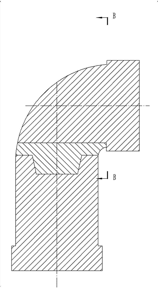
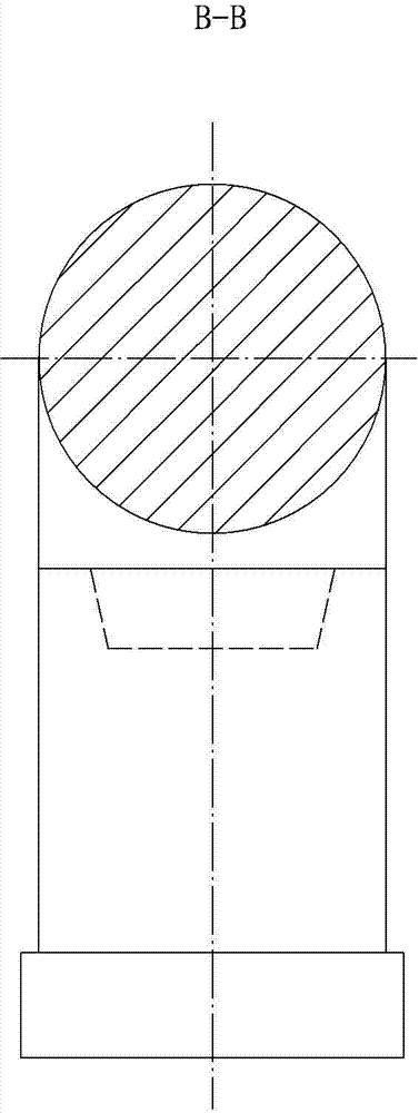
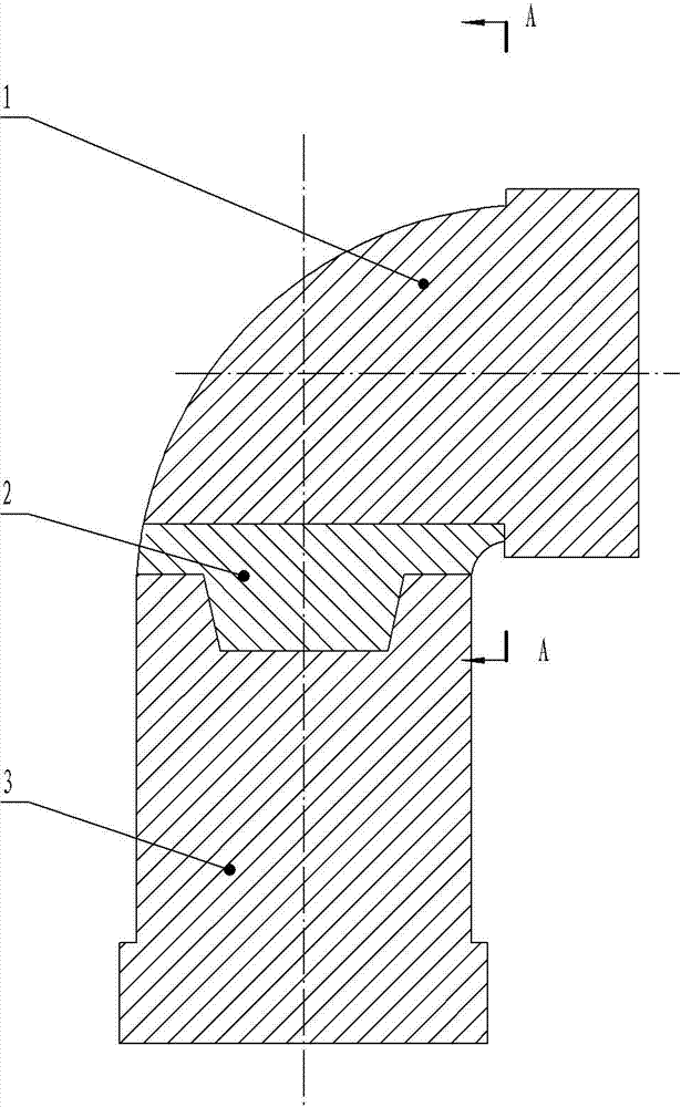
[0016] Embodiment 1 includes a fixed module A 3 composed of two cylinders with a large outer end and a smaller inner end. One outer end is a cylinder, the outer side of the inner end is a ring body with a torus and the outer side is a plug with a cylindrical surface. The fixed module B 1 composed of the composite part is equipped with a movable module 2 between the fixed module A 3 and the fixed module B 1, and the movable module 2 and the fixed module A 3 are joined by a tapered socket and a tapered plug. The connection between the module 2 and the fixed module B 1 is to insert the plug portion on the fixed module B 1 into the groove bottom surface of the movable module 2 which is a cylindrical groove, and the diameter of the groove bottom surface of the movable module 2 is smaller than that of the fixed module B 1 The diameter of the torus of the ring body is 5.5 mm, and the connection between the torus of the ring body of the fixed module B 1 and the cylindrical surface of t...

Embodiment 2

[0017] Embodiment 2 This embodiment is identical to Embodiment 1 except that the diameter of the bottom surface of the groove of the movable module 2 is smaller than the diameter of the annulus of the annulus of the fixed module B 1 by 3 mm, and the remaining parts are identical, and will not be repeated.

Embodiment 3

[0018] Embodiment 3 This embodiment is identical to Embodiment 1 except that the diameter of the bottom surface of the groove of the movable module 2 is smaller than the diameter of the annulus of the ring body of the fixed module B 1 by 8 mm, and the remaining parts are identical, and will not be repeated.

[0019] When closing the mold, the torus of the ring body of the fixed module B1 is engaged with the groove whose bottom surface of the groove of the movable module 2 is cylindrical, because the diameter of the bottom surface of the groove of the movable module 2 is smaller than the torus of the ring body of the fixed module B1 The diameter of the ring, the top of the groove edge of the groove of the movable module 2 will not form a sharp edge, but form two platforms, so that the contact between the fixed module B1 and the movable module 2 is changed from the original line contact to the present surface contact. Contact, the contact area between the two has increased, the p...


PUM

PropertyMeasurementUnit
diameteraaaaaaaaaa

Abstract

The invention discloses a draining pipe elbow die, which comprises a fixed module A, a movable module and a fixed module B, the movable module is arranged on the fixed module A, the lower half part of the fixed module B is spliced with the top half part of the movable module, the fixed module B, the movable module and the fixed module A are spliced to form a core model of the draining pipe elbow die; the draining pipe elbow die has the characteristics that the diameter of a groove bottom surface of the movable module is less than the diameter of a circular ring of an anchor ring of a fixed module B ring body part by 3-8 millimeters, the connection of the anchor ring of the ring body part of the fixed module B and the cylindrical surface of a plug part is a plane or a curved surface; by using the draining pipe elbow die, the problems that formation of the sharp cutting edge shape at the top of groove edge of the movable module groove as well as the movable module enables easy collapse in the prior art can be solved.

Description

technical field [0001] The invention relates to the technical field of injection mold manufacturing, in particular to a core mold for plastic drain pipe elbow injection molding. Background technique [0002] In order to connect the plastic drainage pipe elbow with the straight pipe, its two ends are usually provided with expansion pipe sections for insertion into it. In the injection molding process of this plastic drainage pipe elbow, an outer mold and a core installed in the outer mold are required. The mold encloses a cavity of the drainpipe elbow. After the drainpipe elbow is injection molded, the mandrel must come out of the plastic drainpipe elbow. Because the mandrel of the drainpipe elbow also has a shape with a large middle part and a small shape at both ends. , therefore, this mandrel needs to be composed of multiple modules. The mandrel of the existing drainage pipe elbow has a plan that is a fixed module A composed of two cylinders with a shape like the shape of...

Claims


Application Information

Patent Timeline
Patent Type & Authority Patents(China)
IPC IPC(8): B29C33/76B29C45/36
Inventor 梁士科黄沛锋
Owner GUANGXI WUZHOU WUYI PLASTIC PROD
Learn More