
Groove-type embedded part

A kind of embedded parts, groove technology, applied in the direction of construction, building structure, etc., can solve the problems of inconvenient production and implementation, complex production process, high cost, achieve flexible production and processing, increase contact area, reduce material waste. Effect

Inactive Publication Date: 2013-05-01
GUANGDONG KIN LONG HARDWARE PROD CO LTD
View PDF4 Cites 4 Cited by
  • Summary
  • Abstract
  • Description
  • Claims
  • Application Information

AI Technical Summary

Problems solved by technology

[0002] At present, with the diversified development of building design and the continuous improvement of firmness requirements, the form of embedded parts for buildings is also changing. In the prior art, the embedded parts use welding anchors and press-fit Anchor, the production process is complicated, the cost is high, it brings inconvenience to production and implementation, and it needs to be improved

Method used


Image

  • Groove-type embedded part
  • Groove-type embedded part
  • Groove-type embedded part

Examples


Embodiment 1

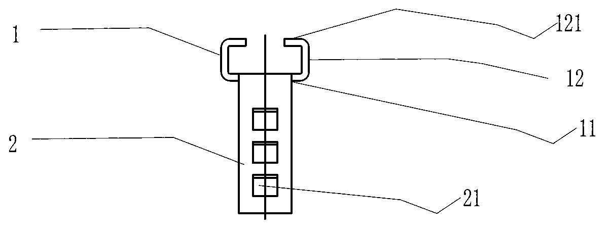
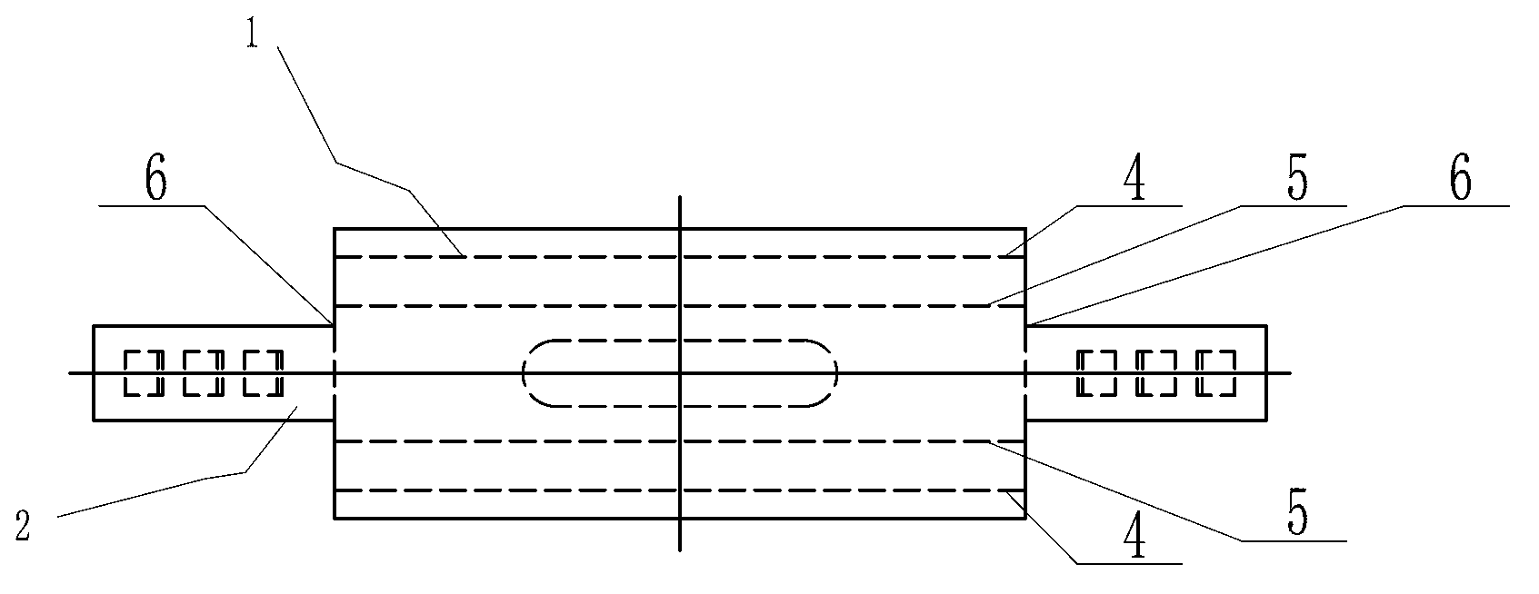
[0036] Such as figure 1 with image 3 As shown, among them, figure 1 It is the front view of the first embodiment of the groove type embedded part of the present invention; figure 2 It is a side view of the first embodiment of the groove-type embedded part of the present invention; image 3 It is an expanded view of the first embodiment of the groove-type embedded part of the present invention.

[0037] The groove-type embedded part of the present invention includes a C-shaped groove 1 and a side wing 2, and the C-shaped groove 1 and the side wing 2 are integrally structured.

[0038] Such as figure 1 As shown, the C-shaped tank 1 includes a base 11 and a side wall 12 . The base 11 is a quadrangle, and its corresponding two sides are connected to the side wings 2 , and the other corresponding sides extend from the side wings 2 in opposite directions to two side walls 12 . The two sidewalls 12 are substantially at a 90-degree angle to the base. Two extension arms 121 ex...

Embodiment 2

[0048] Such as Figure 4 As shown, it is a side view of the groove-type embedded part of the second embodiment of the present invention. Compared with the first embodiment, the present embodiment does not use lugs 21 on the flanks, but uses holes 22 . Holes are opened on the side wings, and the effect of the hole 22 is the same as that of the ear plate 21, which is to increase the contact area with the concrete and improve the strength against pulling out.

Embodiment 3

[0050] Such as Figure 5 As shown, it is a side view of the groove-type embedded part of the third embodiment of the present invention. Compared with the first embodiment and the second embodiment, the side wing 2 is a plane, that is, there is no opening, and there is no ear plate. Another difference is that a support arm 23 is provided on the top of the side wing 2 , and the support arm 23 is basically at an angle of 90 degrees to the side wing 2 , that is to say, it is basically parallel to the base 11 of the C-shaped slot 1 . At this time, the support arm 23 is equivalent to a hook, which increases the contact area with the concrete and improves the strength against pulling out.


PUM


Abstract

The invention relates to a groove-type embedded part, which comprises a C-shaped groove and two side wings. The C-shaped groove comprises a base and two side walls. The two side walls extend from the two sides of the base. Extension arms extend from the front ends of the side walls. The two side walls, the extension arms and the base are integral. By adopting the technical scheme and by adopting integral design and a plate bending and punching technology to realize the production of the embedded part, the groove-type embedded part has the beneficial effects that: 1. plate machining can be used during mass production and the material wastage is reduced by optimizing plate setting; 2. the groove-type embedded part is flexible to produce and manufacture; 3. the machining strength of steel plates is higher than the strength of plates which are produced by adopting the existing techniques such as casting; and 4. the punched holes or small ear plates can increase the area of contact with concrete and the pulling strength is improved.

Description

【Technical field】 [0001] The invention relates to a building component, in particular to a groove-type embedded part. 【Background technique】 [0002] At present, with the diversified development of building design and the continuous improvement of firmness requirements, the form of embedded parts for buildings is also changing. In the prior art, the embedded parts use welding anchors and press-fit Anchor nails have complicated production process and high cost, which brings inconvenience to production and implementation, and really needs to be improved. 【Content of invention】 [0003] In view of the defects of the embedded parts in the prior art, it is necessary to provide an embedded part which is convenient for production and can be produced on a large scale. [0004] To achieve the above object, the present invention adopts the following scheme: [0005] A trough-type embedded part, which includes: a C-shaped trough and two side wings. The C-shaped slot includes a bas...

Claims


Application Information

Patent Timeline
Patent Type & Authority Applications(China)
IPC IPC(8): E04B1/41
Inventor 白宝鲲
Owner GUANGDONG KIN LONG HARDWARE PROD CO LTD
Learn More