Screw pitch error compensating method

A compensation method and pitch error technology, which is applied in the field of pitch error compensation, can solve problems such as limited use, non-uniform and inconsistent pitch error distribution, and achieve good compensation effects

Active Publication Date: 2013-05-01
SHENZHEN A&E INTELLIGENT EQUIP
View PDF4 Cites 6 Cited by
  • Summary
  • Abstract
  • Description
  • Claims
  • Application Information

AI Technical Summary

Problems solved by technology

However, in actual situations, since the pitch error distribution is not uniform, the result of using the linear formula to compensate the pitch error does not match the actual situation
In addition, the above prior art requires that multiple discrete compensation points must be evenly distributed, and the reference origin of the discrete compensation points must be within the range of multiple discrete compensation points, thus limiting the use of the above prior art

Method used


Image

  • Screw pitch error compensating method
  • Screw pitch error compensating method
  • Screw pitch error compensating method

Examples


Embodiment Construction

[0023] The present invention will be described in detail below in conjunction with the accompanying drawings and embodiments.

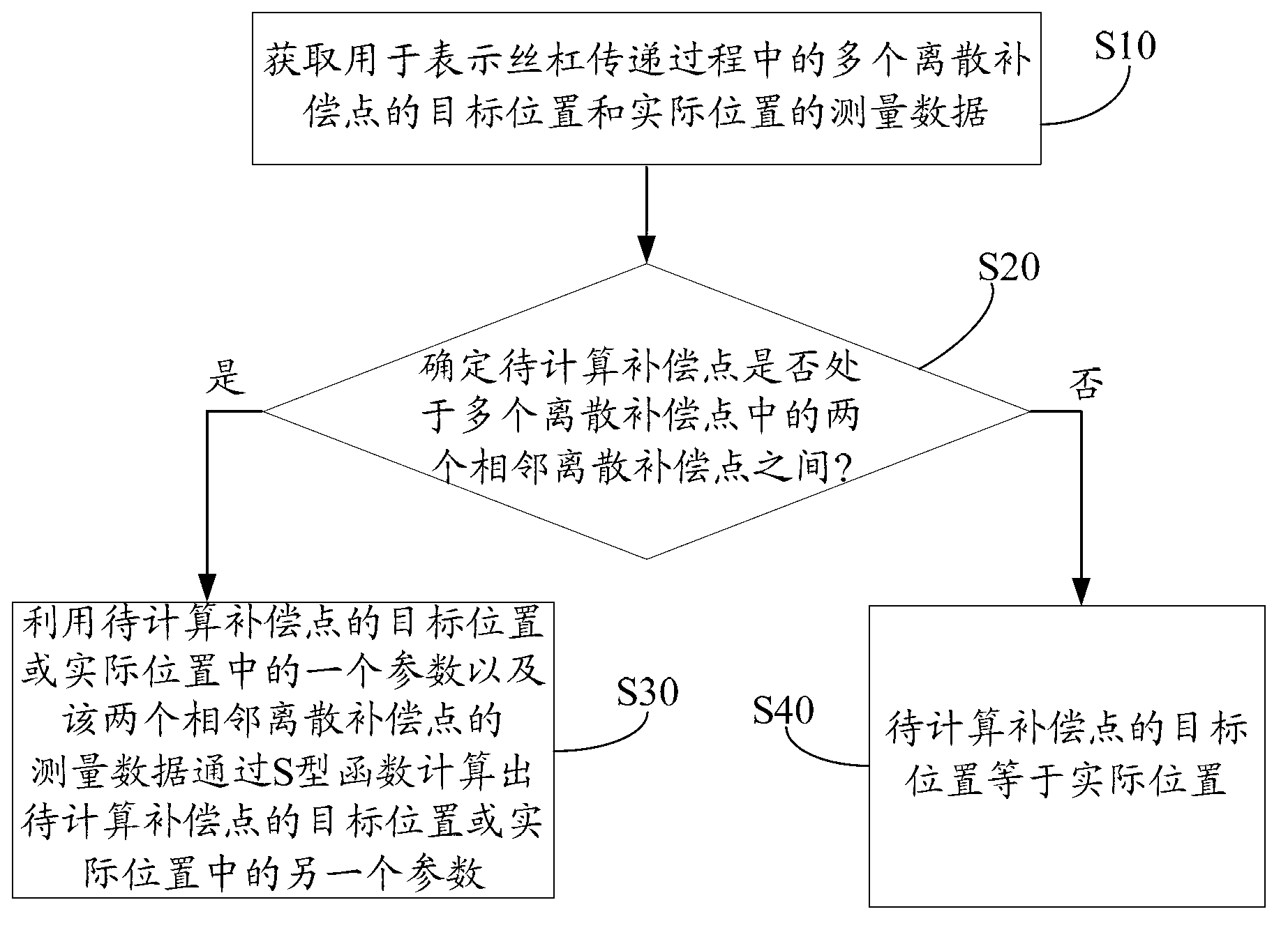
[0024] figure 1 It is a schematic flow chart of an embodiment of the pitch error compensation method of the present invention. Such as figure 1 As shown, the method includes:

[0025] Step S10: Obtain measurement data used to represent target positions and actual positions of multiple discrete compensation points during the screw transmission process.

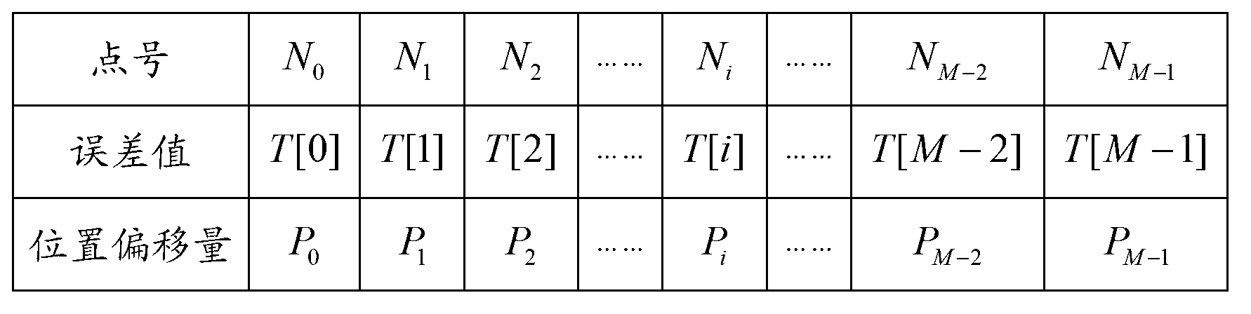
[0026] In this step, multiple target positions are used as control data to control the transmission of the lead screw, and the actual position of the lead screw is measured by laser interferometer or other tools, and then multiple discrete compensation points are obtained, and the multiple The target and actual positions of the discrete compensation points are recorded. For example, see figure 2 , figure 2 yes figure 1 Schematic diagram of the measured data of multiple discrete compensation po...


PUM


Abstract

The invention discloses a screw pitch error compensating method. The method comprises the following steps that measurement data used for showing the target position and the practical position of a plurality of discrete compensation points in the lead screw transferring process is obtained; whether compensation points to be calculated are positioned between two adjacent discrete compensation points in the discrete compensation points or not is determined; and when the compensation points to be calculated are positioned between two adjacent discrete compensation points, the other parameter in the target position or the practical position of the compensation points to be calculated is calculated through a S type function according to the measurement data of the two adjacent discrete compensation points and one parameter in the target position or the practical position of the compensation points to be calculated. Through adopting the mode, the screw pitch error can be compensated in a mode of conforming to the practical condition, so better compensation effects are obtained.

Description

technical field [0001] The invention relates to the field of engineering machinery, in particular to a pitch error compensation method. Background technique [0002] With the development of science and technology, in the field of construction machinery, the CNC system has higher and higher requirements for the machining accuracy of the process, especially for the accuracy of the thread distance. However, due to the manufacturing process of the machine tool itself or long-term wear and tear, there is an error in the thread distance on the lead screw. In order to ensure the precise control of the machine tool by the CNC system, it is necessary to measure and record the pitch error of the screw, and then compensate the pitch error. The existing technology is to measure and record the actual position and target position of multiple discrete compensation points during the screw transmission process, and use a linear formula to perform pitch error compensation on other compensati...

Claims


Application Information

Patent Timeline
Patent Type & Authority Applications(China)
IPC IPC(8): G01B21/16
Inventor 何敏聪黄祥钧万波
Owner SHENZHEN A&E INTELLIGENT EQUIP
Why Eureka
Try Eureka