Measure method for confirming roll angle of revolving body target based on spiral line method

A technology of revolving body and helical line is applied in the measurement field of determining the target roll angle of the revolving body based on the helical line method, which can solve problems such as roll angle error, and achieve the effect of solving the roll angle error and improving the calculation accuracy.

Active Publication Date: 2015-05-13
INST OF OPTICS & ELECTRONICS - CHINESE ACAD OF SCI
View PDF4 Cites 0 Cited by
  • Summary
  • Abstract
  • Description
  • Claims
  • Application Information

AI Technical Summary

Problems solved by technology

[0004] In order to overcome the deficiencies of the above-mentioned prior art, the object of the present invention is to provide a new measurement method for determining the target roll angle of a revolving body based on the helix method, so that it can effectively solve the problems caused by the projected direction line and the center of the revolving body image. The problem of roll angle error caused by line inconsistency further improves the accuracy of roll angle calculation

Method used


Image

  • Measure method for confirming roll angle of revolving body target based on spiral line method
  • Measure method for confirming roll angle of revolving body target based on spiral line method
  • Measure method for confirming roll angle of revolving body target based on spiral line method

Examples


Embodiment Construction

[0017] Embodiments of the present invention are described below in conjunction with the accompanying drawings.

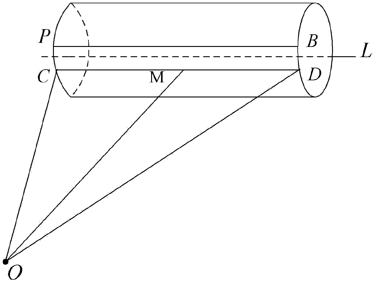
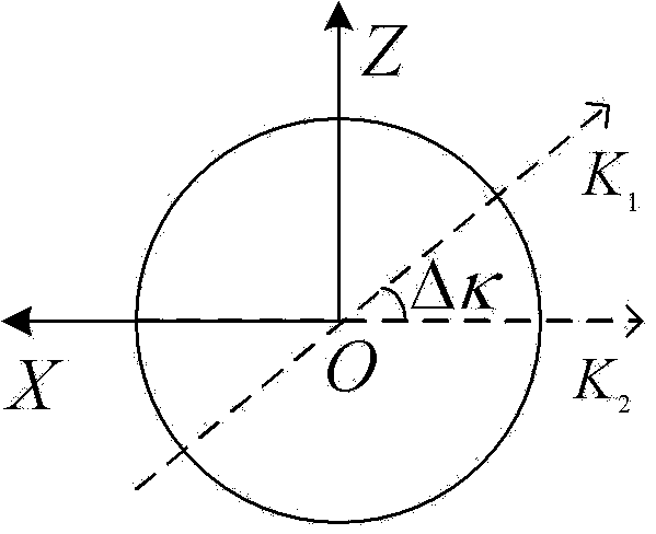
[0018] combined with Figure 1a with Figure 1b It is a schematic diagram of the projection of each vector on the ZOX plane in the present invention, and the implementation technology and process of the present invention are illustrated by using the helix method to measure the target roll angle of the revolving body as an example. Figure 1 includes the origin O, point B, point D, and point M. The target axis L and PB are target projection direction lines, L is the target axis, CD is the image center line, and the three lines are parallel to each other. Azimuth A and E elevation angle E are data measured by theodolite, which cannot be marked in the figure.

[0019] First, according to the traditional helix method of measuring the roll angle, the angle n corresponding to the centerline of the image of the revolving object is obtained, and any point M is determined on...


PUM


Abstract

The invention discloses a measure method for confirming a roll angle of a revolving body target based on a spiral line method. The measure method comprises the following steps: Step S1: Obtaining an angle corresponding to an image center line of the revolving body target based on a traditional spiral line method of measuring the roll angle; Step S2: determining a point on the image center line of the revolving body target, and calculating the azimuth angle and the pitching angle, and obtaining the direction vector of the connecting wire of the point and a camera origin; Step S3: using a cosine matrix to create a carrier coordinate system without regard to the effect of the roll angle, and projecting the direction vector obtained in the Step S2 to the carrier coordinate system, and obtaining the projection vector corresponding to the direction vector; Step S4: calculating the planimetric projection vector formed by the revolving body target center line and the spiral line initiative generating line in the carrier coordinate system, and calculating the included angle of the plane and the projection vector obtained in the Step S3; and Step S5: calculating the difference value of the angle corresponding to the image center line of the revolving body target in the Step S1 and the included angle value in the Step S4.

Description

technical field [0001] The invention relates to the fields of digital image processing, photogrammetry, computer vision and the like, in particular to a measuring method for determining the rolling angle of a revolving object based on a helical line method. Background technique [0002] In military, aerospace and other fields, the three-dimensional attitude of space moving objects is an important technical index reflecting its flight state. Obtaining these indexes is of great significance for analyzing and evaluating the motion characteristics of space objects and further optimizing system design. There are many methods to solve the attitude measurement of the pitch angle and yaw angle of the target, but the measurement of the roll angle of the target is seldom discussed, and it is used for the attitude parameters of space targets such as missiles and rockets. And extremely important. In the measurement of roll angle, there is a method of intersecting measurement with optic...

Claims


Application Information

Patent Timeline
Patent Type & Authority Patents(China)
IPC IPC(8): G01C1/00
Inventor 王超张涯辉何培龙
Owner INST OF OPTICS & ELECTRONICS - CHINESE ACAD OF SCI
Why Eureka
Try Eureka