Supercharge Your Innovation With Domain-Expert AI Agents!

Rapid positioning method for breakover point of insulation resistance of bifilar parallel wound coil

A technology of insulation resistance and positioning method, applied in the direction of measuring electricity, measuring electrical variables, measuring devices, etc., can solve problems such as hidden dangers of production efficiency and product reliability, short circuit of two sets of coils, conduction of insulation resistance, etc., to achieve high efficiency, Simple to use effects

Active Publication Date: 2013-05-01
SUZHOU CHANGFENG AVIATION ELECTRONICS
View PDF4 Cites 1 Cited by
  • Summary
  • Abstract
  • Description
  • Claims
  • Application Information

AI Technical Summary

Problems solved by technology

[0003] However, insulation resistance conduction often occurs during the test, resulting in a short circuit between the two sets of coils
Through investigation and analysis, it can be concluded that there is conduction between the two sets of enameled wires of the coil, but the conduction point cannot be accurately located.
Because the diameter of the enameled wire is only 0.07mm, and the number of turns of the coil usually reaches thousands of turns, finding a micron-level conduction point on an enameled wire of several meters or even tens of meters is tantamount to finding a needle in a haystack. In the face of several questions such as the number of conduction points, the coil had to be removed and rewound, which brought hidden dangers to future production efficiency and product reliability.

Method used


Image

  • Rapid positioning method for breakover point of insulation resistance of bifilar parallel wound coil
  • Rapid positioning method for breakover point of insulation resistance of bifilar parallel wound coil

Examples


Embodiment Construction

[0016] The present invention is described in detail below by specific embodiment:

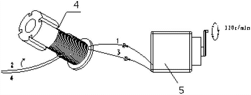
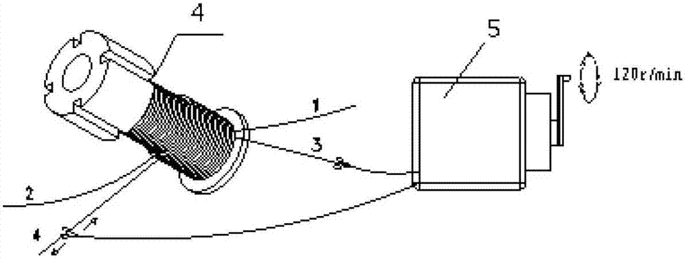
[0017] The present invention adopts the commonly used testing instrument for insulation resistance, takes the double-wire parallel winding coil with insulation resistance conduction as a sample, and then divides it into "two steps" to decompose and locate the conduction point of the insulation resistance of the enameled wire. Through the two-step test method of "shaking while retreating" and "shaking while sliding", quickly and accurately locate the conduction point of the insulation resistance of the double-wire and winding coil.

[0018] Specific process

[0019] step 1

[0020] see figure 1 , Use the method of "shaking while retreating" to decompose the coil. "Shaking" refers to shaking the megohmmeter at a speed of 120r / min to test the insulation resistance, and "retreating" refers to withdrawing the coil. The detailed process is that the double-wire winding coil has four lead ends, that...


PUM


Abstract

The invention belongs to a positioning technology for a breakover point of insulation resistance of a coil, and relates to a rapid positioning method for a breakover point of the insulation resistance of a bifilar parallel wound coil. Heads of two groups of enamelled wires are respectively connected to an anode and a cathode of a tramegger and are subjected to continuous insulation test, the tail parts of the two groups of enamelled wires are held at the same time to slowly withdraw the coil, at the initial stage of coil withdrawing, the insulation resistance is 0; along with the withdrawing of the coil, the two groups of enamelled wires are separated to cause breakover point disconnection, and the insulation resistance rises to infinite, so that the breakover point of the insulation resistance is locked within a smaller range; and then the anode of the tramegger is connected to the end part of one group of enamelled wire of the coil, the cathode of the tramegger is slid in a contact mode slowly and circularly on the locked enameled wire to and fro, and meanwhile the tramegger continuously carries out insulation test, and once the cathode of the tramegger is contacted with the breakover point of the insulation resistance, an indicator of the tramegger swings to zero immediately so as to precisely lock the breakover point. The positioning method disclosed by the invention is simple in operation and high in precision and has greater practical application value.

Description

technical field [0001] The invention belongs to the coil insulation resistance conduction point positioning technology, and relates to a double-wire winding coil insulation resistance conduction point rapid positioning method. Background technique [0002] For instruments such as speed sensors, vibration sensors, and transformers, the core part of the induction test is the coil. Since the double-wire parallel-wound coil can simultaneously output two sets of test signals and transmit them to different controllers, it is widely used in the field of instrumentation. The double-wire winding coil means that two sets of enameled wires are wound on the same skeleton at the same time, and finally four wires are drawn out to connect to the connector. [0003] However, insulation resistance conduction often occurs during the test, resulting in a short circuit between the two sets of coils. Through investigation and analysis, it can be concluded that the two sets of enameled wires of...

Claims


Application Information

Patent Timeline
IPC IPC(8): G01R31/02
Inventor 李闯傅海波
Owner SUZHOU CHANGFENG AVIATION ELECTRONICS
Features
  • R&D
  • Intellectual Property
  • Life Sciences
  • Materials
  • Tech Scout
  • Unparalleled Data Quality
  • Higher Quality Content
  • 60% Fewer Hallucinations
Learn More