
Multi-station powder coating machine for inner wall of spiral lamp tube

A multi-station technology inside the lamp tube, which is applied in the manufacture of tubes/lamp screens and the application of luminescent coatings. It can solve the problems affecting the quality requirements of lamp tubes, uneven thickness of phosphor powder, powder accumulation, etc., and achieve improved powder coating. Quality, uniform powder coating, ensuring the effect of powder coating

Inactive Publication Date: 2013-05-01
浙江力胜电子科技有限公司
View PDF5 Cites 2 Cited by
  • Summary
  • Abstract
  • Description
  • Claims
  • Application Information

AI Technical Summary

Problems solved by technology

Commonly known as powder coating is to coat the required phosphor powder in the glass lamp tube. The quality requirement is that the phosphor powder coated must be uniform in thickness, and there is no powder accumulation or powder removal in the lamp tube; the powder coating technology used today is to put The prepared fluorescent powder is sprayed in from one end of the glass lamp tube opening with a spray gun, and flows out naturally from the other end, and then hangs the lamp tube upside down to let the excess phosphor powder in the lamp tube flow out naturally and dry on the drying line. Powder process, because the excess fluorescent powder in the lamp tube is naturally flowed out by hanging the lamp tube upside down, it will cause uneven thickness of the phosphor powder, especially because the spiral lamp tube has many curved parts, so it is in the curved position. Parts and easy to cause powder accumulation, which affects the quality requirements of the entire lamp tube

Method used


Image

  • Multi-station powder coating machine for inner wall of spiral lamp tube
  • Multi-station powder coating machine for inner wall of spiral lamp tube

Examples


Embodiment Construction

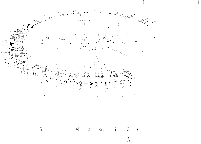
[0017] exist figure 1 and figure 2 Among them, a powder coating machine for the inner wall of a multi-station spiral lamp tube, including a turntable 8 along the circumference and a drying channel 1, a plurality of station devices are evenly distributed on the turntable 8, and a gas collecting box 2 is arranged on the station device. The gas collection box 2 is connected with an air intake pipe 3, and the gas collection box 2 is provided with a row of four corrugated pipes 4, and a rotating shaft 5 is provided on the station device. , the workpiece seat 6 includes four pins 61 arranged in a rectangle, and the four pins 61 are connected to the end of the rotating shaft 5 through a fixing plate 62 . A powder feeder 7 is provided on the side of the turntable of the circumference before entering the drying channel 1 .

[0018] The embodiment of the present invention adopts artificial powdering, and after the operator powders the spiral lamp tube through the powdering machine 7...


PUM


Abstract

The invention discloses a multi-station powder coating machine for the inner wall of a spiral lamp tube. The multi-station powder coating machine comprises a turntable and a drying channel which are along the circumference; a plurality of station devices are uniformly distributed on the turntable; the multi-station powder coating machine is characterized in that air collection boxes are arranged on the station devices; the air collection boxes are connected with air inlet pipes; a row of corrugated pipes are arranged on the air collection boxes; a rotating shaft is arranged on each station device; a workpiece seat is arranged on each rotating shaft; and each workpiece seat is aligned with the outlet of each corrugated pipe. By the multi-station powder coating machine, air can be blown to a spiral lamp tube workpiece which is subjected to powder coating by the corrugated pipes which can be bent at random angles; powder is coated on the inner wall of the lamp tube uniformly without accumulated powder or flow mark; the powder coating quality of the inner wall of the lamp tube and the light efficiency of the lamp tube are improved; and the continuous automatic operation of powder coating and drying of the spiral lamp tube can be realized.

Description

technical field [0001] The invention relates to a production equipment of an electric light source product, which is a powder coating equipment for the inner wall of a spiral lamp tube. Background technique [0002] At present, in the production process and technology of the spiral energy-saving lamp tube, the powder coating process is a key technology, and the quality of the powder coating directly affects the quality of the tube. Commonly known as powder coating is to coat the required phosphor powder in the glass lamp tube. The quality requirement is that the phosphor powder coated must be uniform in thickness, and there is no powder accumulation or powder removal in the lamp tube; the powder coating technology used today is to put The prepared fluorescent powder is sprayed in from one end of the glass lamp tube with a spray gun, and flows out naturally from the other end, and then hangs the lamp tube upside down to let the excess phosphor powder in the lamp tube flow out...

Claims


Application Information

Patent Timeline
Patent Type & Authority Applications(China)
IPC IPC(8): H01J9/22
Inventor 祝江土
Owner 浙江力胜电子科技有限公司
Learn More