Corner reflection unit and control method

A control method and corner reflection technology, applied in the direction of electrical components, antennas, etc., can solve problems such as unbalanced link budget two-way communication, inability to achieve effective reception of node signals, etc., to achieve overall link performance improvement, tracking performance improvement, and system low cost effect

Active Publication Date: 2013-05-01
北京芯同汇科技有限公司
View PDF3 Cites 17 Cited by
  • Summary
  • Abstract
  • Description
  • Claims
  • Application Information

AI Technical Summary

Problems solved by technology

If the PA is only added to one side of the communication node, it may be that the sensitivity of one side of the node is lower than that of the other side, even under the condition of channel codec, it will cause multiple retransmissions between communication nodes, so that the link Two-way communication in the budget is out of balance
In addition, in the prior art, the way of fixing the direction of the corner reflector is usually used to realize the effective reception of the signal of the communication node, but for the mobile node, since the node is in motion, the corner reflector cannot be set in advance. Signal reception azimuth or angle, therefore, for a mobile node, the corner reflection antenna in the prior art cannot achieve effective reception of the node signal

Method used


Image

  • Corner reflection unit and control method
  • Corner reflection unit and control method
  • Corner reflection unit and control method

Examples


Embodiment 1

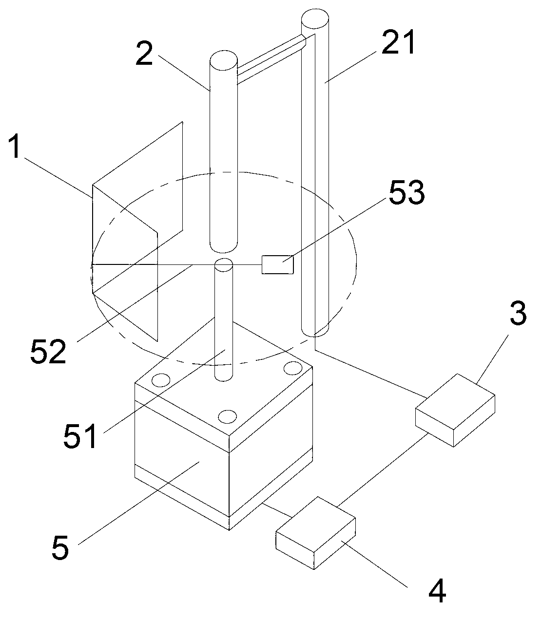
[0017] Such as figure 1 As shown, the corner reflector in the present invention includes: a corner reflector 1 , an omnidirectional antenna 2 , a signal receiver 3 connected to the omnidirectional antenna 2 , a motor controller 4 and a motor 5 . The output shaft 51 of the corner reflector 1 and the motor 5 is connected through the connecting part 52, so that the output shaft 51 of the motor 5 can drive the corner reflector 1 to rotate when rotating, and the length of the connecting part 52 can be adjusted to adjust The size of the circle of rotation of the corner reflector 1 is to change the distance between the corner reflector 1 and the omnidirectional antenna 2 . The omnidirectional antenna 2 can be fixed at the center of rotation of the corner reflector 1 through the antenna bracket 21 , so as to realize the reception of the wireless signal to be tracked through the corner reflector 1 . The signal receiver 3 receives the wireless signal to be tracked, extracts information...

Embodiment 2

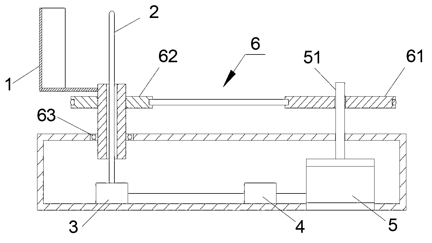
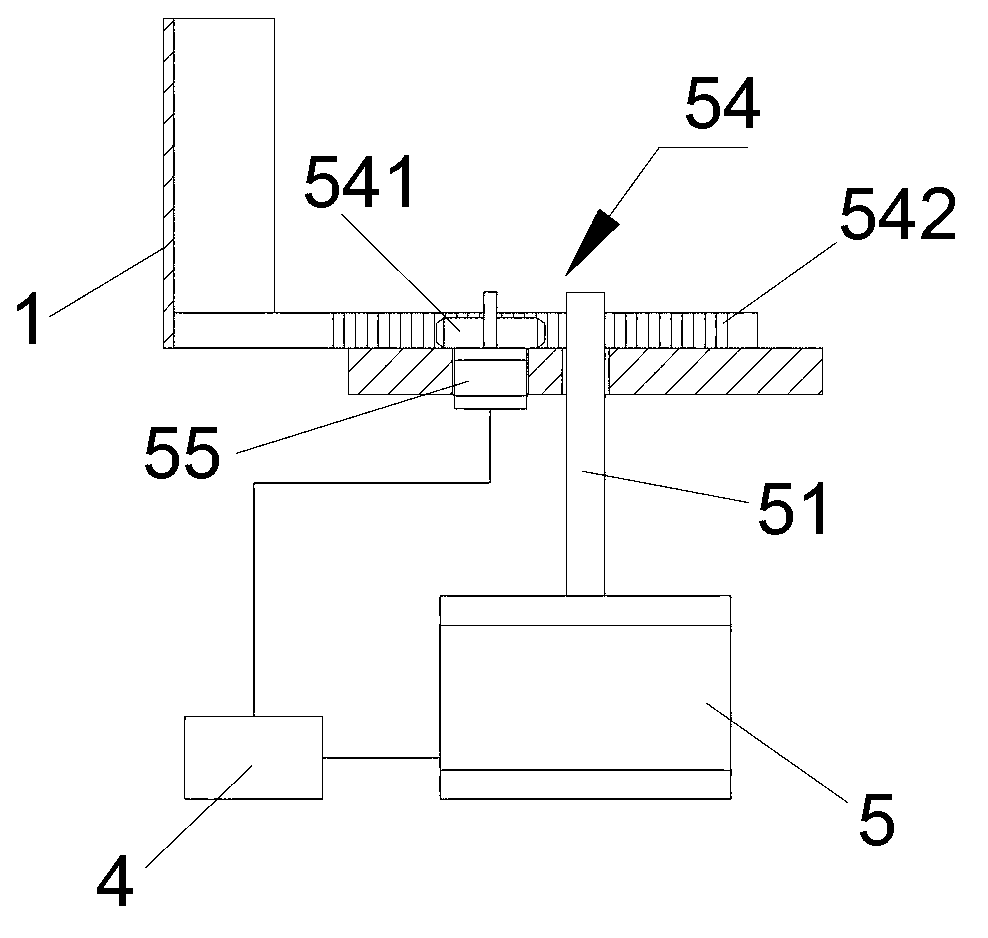
[0022] Such as figure 2As shown, in this embodiment, except that the output shaft 51 of the motor 5 is directly connected with the corner reflector 1 in Embodiment 1, the connection between the output shaft 51 and the corner reflector 1 can also be carried out through the transmission device 6, The output shaft 51 is connected to the driving end 61 of the transmission device 6 , and the driven end 62 of the transmission device 6 is connected to the corner reflector 1 , so that the output shaft 51 drives the corner reflector 1 to rotate around the omnidirectional antenna 2 through the transmission device 6 . Transmission device 6 can adopt multiple transmission forms, as, belt transmission device and pinion and rack transmission device. Among them, in order to make the driven end 62 drive the corner reflector 1 to rotate more smoothly, the driven end 62 of the transmission device 6 can be supported by the supporting surface of the support frame 7, in order to ensure the flexib...

Embodiment 3

[0024] According to another aspect of the present invention, a corner reflection control method is also provided, including:

[0025] Step S101: Refer to figure 1 In the corner reflector, when the corner reflector is in the starting state, the motor controller 4 drives the motor 5 to drive the corner reflector 1 to rotate around the omnidirectional antenna 2 for one revolution, and during this one revolution, signal The receiver 3 receives multiple signals of the wireless signal to be tracked when the corner reflector 1 is at different angles, and feeds back the signal strength and / or link quality of the wireless signal to be tracked to the motor controller 4 . The motor controller 4 performs data processing based on the received multiple signal information and the corresponding rotation angles of the multiple motor output shafts 51 according to preset conditions (such as: maximum signal strength RSSI and / or optimal link quality LQI). The angle of the motor output shaft 51 co...


PUM


Abstract

The invention discloses a corner reflection unit and a control method. The corner reflection unit comprises a corner reflection plate, an omnidirectional antenna, a signal receiver, a motor driving device, a motor controller and a motor. The omnidirectional antenna receives a wireless signal to be tracked through the corner reflection plate; the signal receiver feeds back the strength and the direction information of the wireless signal to be tracked to the motor controller according to the received wireless signal to be tracked; and the motor controller drives the motor according to relevant information, so that an output shaft drives the corner reflection plate to rotate around the omnidirectional antenna for a corresponding angle. Because a closed-loop control method is formed between the signal receiving end of the corner reflector and the driving device which controls the corner reflector to rotate, the signal can be fed back in time when the corner reflector is at different positions or in different angles, so that the appropriate adjustment to the optimal signal receiving position is met, the effects that the system cost is lower and the tracking performance is improved are achieved, and the overall performance of the system is improved.

Description

technical field [0001] The invention relates to the field of wireless communication, in particular to a corner reflection device and a control method for the corner reflection device. Background technique [0002] Whether in wireless communication or in the field of radar, the sensitivity of the receiver is a very important indicator. Therefore, how to effectively improve the sensitivity of the receiver is an important goal in system design. Generally, without considering the signal processing gain, to increase the transmission distance of wireless communication or the detection distance of radar, it is often by adding PA (power amplifier) ​​at the transmitting end, or adding LNA (low noise amplifier) ​​at the receiving end, etc. It has been realized, but the above method is conventional but not universally suitable. The reason is that adding PA at the transmitting end will lead to a decrease in signal quality (non-linearity leads to an increase in error vector magnitude [E...

Claims


Application Information

Patent Timeline
Patent Type & Authority Applications(China)
IPC IPC(8): H01Q19/15H01Q3/20
Inventor 何林刘亚郡金红谦韩浩
Owner 北京芯同汇科技有限公司
Why Eureka
Try Eureka