Transformer inductive reactive power stepped control device and method

A technology of inductive reactive power and control device, applied in reactive power adjustment/elimination/compensation, reactive power compensation and other directions, it can solve the problems of poor reliability, less harmonic current, and easy damage, to avoid burning phenomenon and respond Fast and reliable results

Active Publication Date: 2013-05-01
DATONG POWER SUPPLY BRANCH SHANXI ELECTRIC POWERCO +1
View PDF4 Cites 8 Cited by
  • Summary
  • Abstract
  • Description
  • Claims
  • Application Information

AI Technical Summary

Problems solved by technology

[0003] At present, there are mainly three kinds of reactive power compensation control technologies: one is to use the AC contactor as the switching actuator of the fixed power capacitor, but because of the large impact current when it is put in, it will generate overvoltage when it is cut off, and it will be easily damaged or even welded. High noise, high equipment failure rate, poor reliability, and relatively prone to overcompensation and undercompensation problems
The second is to use the thyristor instead of the AC contactor as the switching actuator, which ensures that the capacitor bank is put into operation near the voltage zero zone, thereby avoiding the generation of the closing inrush current, and the cutting is completed when the current crosses zero, avoiding the transient overvoltage The emergence of this function meets the requirements of zero-crossing switching of capacitors. In addition, since there is no limit to the number of triggers of the thyristor, quasi-dynamic compensation can be realized (response time is in milliseconds), so it is suitable for frequent switching of capacitors. It is very suitable for frequently changing load conditions and has a qualitative leap compared to AC contactors; however, solid state relays have a fatal weakness in their application: the conduction voltage drop of the thyristor is about 1V when the power is on. The loss is very large. Due to the large power consumption, it is necessary to dissipate heat to avoid the thermal breakdown of the PN junction. In order to cool down, a radiator with a large area is required, and even a fan is required for forced ventilation.
The third is the static var generator that has just emerged in recent years. Its main body is a voltage source inverter. The thyristor can be turned off properly to convert the DC voltage on the capacitor into a three-dimensional voltage synchronized with the power system voltage. Phase-to-phase AC voltage, and then connected to the power grid in parallel through reactors and transformers, and properly controlling the output voltage of the inverter can flexibly change its operating conditions, making it in a capacitive, inductive or zero-load state, theoretically static without The power generator responds faster, has less harmonic current, and can still inject large reactive power into the system when the system voltage is low; however, due to its complicated control technology, it has great reliability and economical advantages. deficiencies such that such compensation techniques are rarely used in the market

Method used


Image

  • Transformer inductive reactive power stepped control device and method
  • Transformer inductive reactive power stepped control device and method
  • Transformer inductive reactive power stepped control device and method

Examples


Embodiment Construction

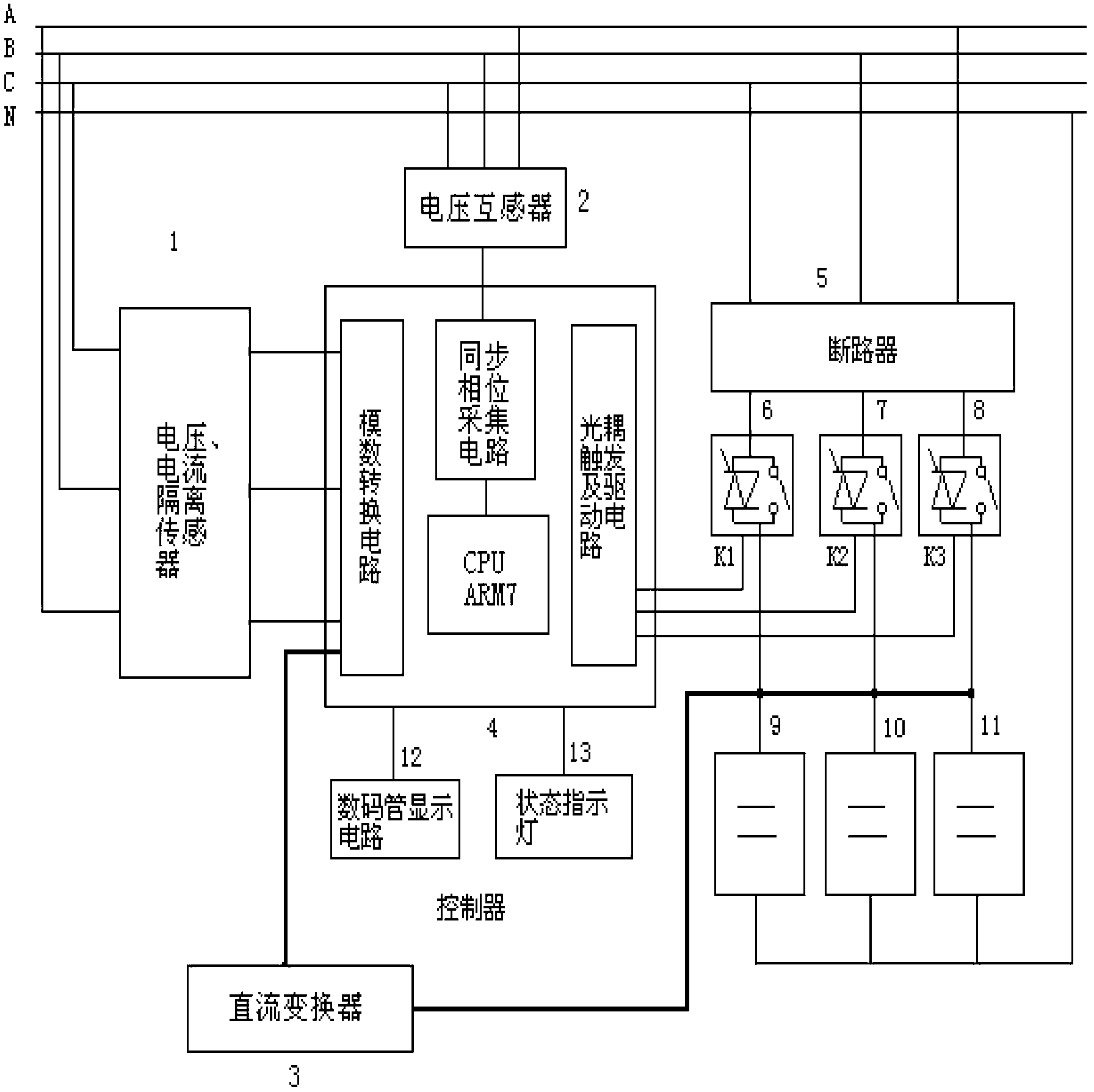
[0049] figure 1 It is a structural diagram of a stepwise control device for inductive reactive power of a transformer in a specific embodiment of the present invention. Such as figure 1 As shown, the transformer inductive reactive power step control device in the specific embodiment of the present invention includes: voltage / current isolation sensor 1, voltage transformer 2, DC converter 3, controller 4, circuit breaker 5, composite switch 6- 8. Power capacitor bank 9-11, digital tube display circuit 12 and status indicator light 13, etc.

[0050] Below is the combination figure 1 To introduce the above structural modules in detail:

[0051] The voltage / current isolation sensor 1 includes voltage / current isolation sensors corresponding to each of the three phase lines. phase voltage signal.

[0052] The voltage transformer 2 is used to step down the three-phase voltage to a low-voltage AC voltage, about 6V, as an input terminal signal of the synchronous phase acquisition ...


PUM


Abstract

The invention discloses a transformer inductive reactive power stepped control device and method. The transformer inductive reactive power stepped control device and method have the advantages that the rapid automatic stepped switching of multiple groups of capacitors are realized, the accuracy is high, the response speed is fast, the power consumption is low, the cost is low, the reliability is high and the requirements on the rapidness and the real-time performance of the reactive compensation of low-voltage transformers are satisfied.

Description

technical field [0001] The invention belongs to the technical field of low-voltage dynamic reactive power compensation, and in particular relates to a stepwise control technology of transformer inductive reactive power. Background technique [0002] In recent years, due to the increase of grid capacity, the requirement for grid reactive power is also increasing day by day. Reactive power supply, like active power supply, is an indispensable part to ensure power system power quality, voltage quality, reduce network loss and safe operation. Transformer is an important pivotal part in power transmission, so the problem of reactive power balance is particularly important. When the reactive power balance on the bus side of the transformer is out of adjustment and the power factor decreases, the line loss increases, the power equipment cannot be used reasonably, and the terminal voltage of the user drops. In serious cases, it will cause equipment damage and system disconnection....

Claims


Application Information

Patent Timeline
Patent Type & Authority Applications(China)
IPC IPC(8): H02J3/18
CPCY02E40/30
Inventor 宋宏伟王启银王晓强王旭
Owner DATONG POWER SUPPLY BRANCH SHANXI ELECTRIC POWERCO
Why Eureka
Try Eureka