

Method and circuit for limiting output power of impulsive discharge
A technology of output power and discharge circuit, applied in battery circuit devices, circuit devices, current collectors, etc., can solve the problems of reduced reliability, poor accuracy, damaged devices, etc.
- Summary
- Abstract
- Description
- Claims
- Application Information
AI Technical Summary
Problems solved by technology
Method used
Image

Examples
specific Embodiment approach
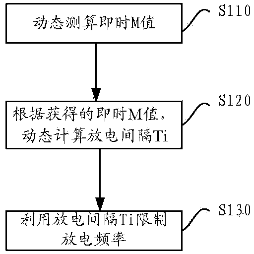
[0023] See image 3 , Figure 4 and Figure 5 , a specific embodiment of a method for limiting the output power of a pulse discharge, the method comprising:
[0024] Step S110: Dynamically calculate the instant M value;
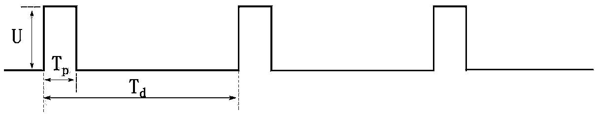
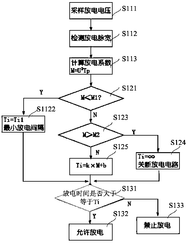
[0025] like figure 1 As shown, the digital control circuit 50 obtains the discharge voltage value U through the voltage detection circuit 40, and the discharge pulse width Tp detected by the discharge pulse width detection circuit 60, by the formula M=U 2 Tp operation obtains instant M value (instantaneous discharge coefficient); Here and the operation in follow-up steps, as those skilled in the art can know, it can adopt the mode of software to realize, also can adopt the mode of hardware to realize;
[0026] Specifically, as Figure 5 As shown, step S110 includes:
[0027] Step S111, the voltage detection circuit 40 samples the discharge voltage;
[0028] Step S112, the discharge pulse width detection circuit 60 samples to obtain the discharge pulse ...
PUM
 Abstract
Description
Claims
Application Information