Double roller cage for a double-row cylinder roller bearing with mass compensation

A cylindrical roller bearing, double-comb technology, applied in the direction of roller bearings, bearing elements, shafts and bearings, to achieve the effect of mass distribution avoidance

Inactive Publication Date: 2013-05-01
SCHAEFFLER TECH AG & CO KG
View PDF6 Cites 4 Cited by
  • Summary
  • Abstract
  • Description
  • Claims
  • Application Information

AI Technical Summary

Problems solved by technology

However, due to the slope of the webs of a support row and the mounting grooves on the side of th

Method used


Image

  • Double roller cage for a double-row cylinder roller bearing with mass compensation
  • Double roller cage for a double-row cylinder roller bearing with mass compensation
  • Double roller cage for a double-row cylinder roller bearing with mass compensation

Examples


Embodiment Construction

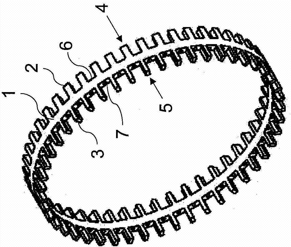
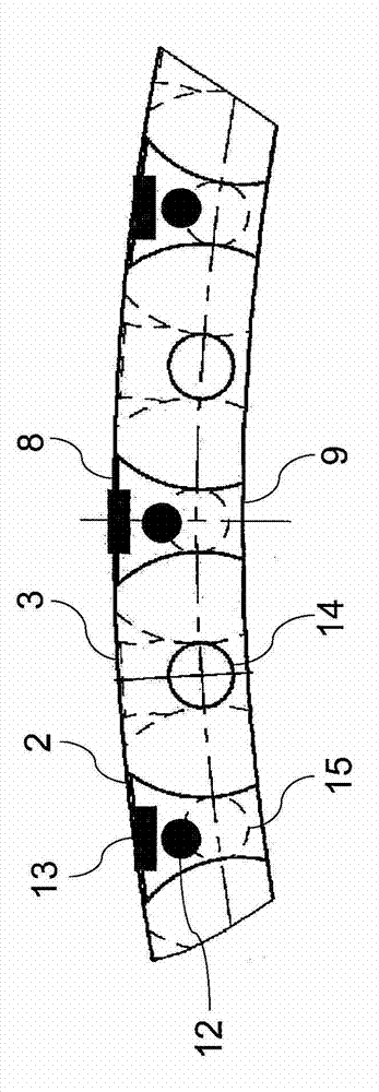
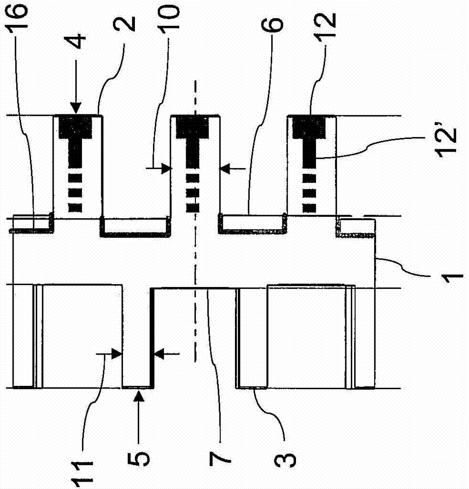
[0026] figure 1 The double-comb cage for double-row cylindrical roller bearings shown in, for example, made of brass in one piece and combined into a ring, includes a central ring member 1, which protrudes axially from both sides of the ring member Splices 2, 3 staggered from each other. The webs 2, 3 on the two axial sides of the cage are arranged evenly distributed on the circumference and correspondingly form bearing rows 4, 5 for rolling elements or cylindrical rollers not shown. Every two adjacent webs 2 or 3 form receiving pockets 6 or 7 for cylindrical rollers. In order to clamp and support the cylindrical rollers in the receiving pockets 6, 7, such as figure 2 As shown in, the tabs 2, 3 can be contoured in a manner known per se between the radially outer bottom side 8 and the radially inner bottom side 9. The outer ring and the inner ring of the cylindrical roller bearing, which are not shown, are likewise implemented in a manner known per se and will not be described...


PUM


Abstract

The invention relates to a double roller cage for a double-row cylinder roller bearing, with a central ring part (1) from which webs (2, 3) protrude axially on both sides, wherein the webs (2; 3) of one side in each case form a row of bearings (4; 5) together with the rolling bearings arranged there, wherein every two adjacent webs (2; 3) of a row of bearings (4; 5) delimit a receiving pocket (6; 7) for a rolling bearing, and in which, at least in one row of bearings (5), the webs (3) are designed so as to taper in the circumferential direction for a radial filling of the receiving pockets (7) with the rolling bearings. So that the double roller cage has satisfactory running behaviour and is relatively simple and cost-effective to produce, recesses (12, 12', 13, 14, 16) are formed on the other of the two rows of bearings (4; 5) in order to produce a symmetrical mass distribution between the two rows of bearings (4; 5).

Description

Technical field [0001] The present invention relates to a double-comb cage for double-row cylindrical roller bearings, which has a central ring member from which lugs extend axially from both sides of the ring, wherein the lug on one side is arranged in The rolling bodies there together correspondingly form a supporting row, wherein every two adjacent webs of the supporting row delimit receiving pockets for the rolling bodies, and wherein the webs are in the circumferential direction in at least one supporting row It is narrowly configured to fill the receiving pockets radially with rolling elements. Background technique [0002] Multi-row cylindrical roller bearings are already known. They are used, for example, in larger automobile transmissions, mechanical equipment transmissions or machine tools, for example as supporting rollers in rolling equipment, where rolling bearings bear high radial loads and, if necessary, axial loads and / or high speeds . In this type of bearing, ...

Claims


Application Information

Patent Timeline
IPC IPC(8): F16C33/48F16C33/49F16C33/46F16C43/06F16C19/28
CPCF16C33/467F16C33/49F16C19/28F16C33/494F16C43/06F16C33/46F16C33/48F16C43/065
Inventor 卡尔·穆勒维尔纳·罗曼
Owner SCHAEFFLER TECH AG & CO KG
Why Eureka
Try Eureka