Piezoelectric on-off valve type jetting dispensing head

A technology of piezoelectric switch and injection point, which is applied in coatings and devices for coating liquid on the surface, etc., can solve the problems of time-consuming, re-centering, and only two pieces of piezoelectric ceramics with exactly the same size can be used. Achieve the effect of small nozzle diameter

Active Publication Date: 2013-05-08
XIAMEN UNIV
View PDF8 Cites 12 Cited by
  • Summary
  • Abstract
  • Description
  • Claims
  • Application Information

AI Technical Summary

Problems solved by technology

Although this kind of amplification mechanism has a simple structure, there are several problems that are difficult to overcome: first, it fixes two piezoelectric ceramics together, so only two piezoelectric ceramics with exactly the same size can be used in actual use; Second, because the front end of the triangular block needs to fix the striker, and the striker needs to be vertically aligned with the nozzle to work effectively, so the total length of the mechanism can only be changed within a small range, so that this type of mechanism can only use some kind of fixed Third, in order to achieve good spraying, adjusting the centering of the striker to the nozzle is very important but also very time-consuming. The mechanism must replace the front cover with the triangular The block is removed together, so the striker must be re-centered after reinstallation

Method used


Image

  • Piezoelectric on-off valve type jetting dispensing head
  • Piezoelectric on-off valve type jetting dispensing head
  • Piezoelectric on-off valve type jetting dispensing head

Examples


Embodiment Construction

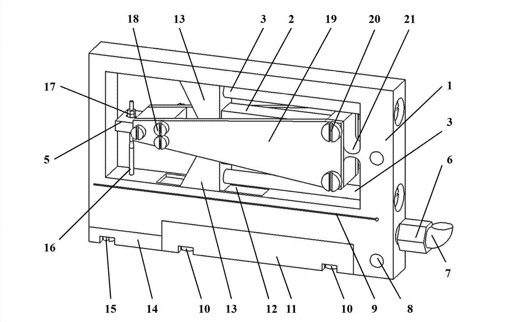
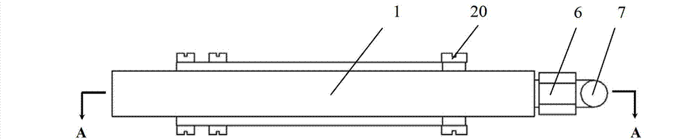
[0015] see Figure 2-5 , the embodiment of the present invention is provided with substrate 1, piezoelectric ceramics 2, pull rod 3, triangular block 5, heating block 11, block 13, nozzle 14, striker 16, flexible hinge 21 and liquid supply device; The substrate 1 is provided with In the flexible hinge 21, two piezoelectric ceramics 2 are respectively pre-tightened on the two arms of the flexible hinge 21 through a stopper 13. The front end of each piezoelectric ceramic 2 is respectively provided with a stopper 13, and the stopper 13 is fixed by a pull rod 3 on the two arms of the flexible hinge 21. On the base 1 and embedded in the block guide groove 12 on the edge of the inner frame of the base 1, the nozzle 14 is fixed on the lower front end of the base 1 through the nozzle fixing bolt 15, and has screw holes that can fix different forms of external nozzles. Both sides of base body 1 are provided with cover plate 19 respectively, and the rear ends of 2 cover plates 19 are fi...


PUM


Abstract

The invention discloses a piezoelectric on-off valve type jetting dispensing head, and relates to a dispensing device mainly for the quick assembly of electronic chips. The jetting dispensing head is provided with a base, two piezoelectric ceramics, pull rods, a triangular block, a heating block, stop blocks, a nozzle, a firing pin, a flexure hinge and a liquid supply device, wherein the base is provided with the flexure hinge, two piezoelectric ceramics are pre-tensioned on two arms of the flexure hinge respectively through stop blocks, the stop blocks are arranged in the front end of the piezoelectric ceramics respectively, and are fixed on the base by the pull rods and embedded in stop blocks guide groove of the inner frame edge of the base; the nozzle is fixed on the front end under the base; cover plates are arranged on two sides of the base respectively, the rear ends of two cover plates are fixed on two arms of the flexure hinge by bolts, and the triangular block are fixed on the front end of two cover plates; the firing pin is arranged on the front end of the triangular block; the heating block is fixed on the lower part of the base; the liquid supply device is provided with a colloidal runner, an inlet conversion adapter and an inlet hose; and the liquid supply device is arranged on the lower part of the base, a heat-insulating groove is arranged between the base and the liquid supply device, and the colloidal runner is externally connected with the liquid supply device through the inlet conversion adapter and the inlet hose.

Description

technical field [0001] The invention relates to a dispensing device mainly used for rapid packaging of electronic chips, in particular to a piezoelectric switch valve type jet dispensing head. Background technique [0002] Dispensing machine is a commonly used equipment in the processing and packaging of electronic products. The dispensing methods of existing fluid dispensing machines are generally divided into contact type and non-contact type. The principle of the contact glue dispenser is to push the fluid through needles of different apertures to contact the substrate and components for dispensing by a certain air pressure, or to transfer the glue to the required part for bonding by dipping the needle tip. The method of contact dispensing has the problems of easy interference between the needle and the substrate, the viscosity of the colloid is greatly affected by temperature, and the problem of low efficiency caused by stringing phenomenon and vertical movement. The n...

Claims


Application Information

Patent Timeline
Patent Type & Authority Applications(China)
IPC IPC(8): B05C5/02B05C11/10
Inventor 吴德志李益盼蔡建法王小萍杜晓辉虞凌科周如海王凌云孙道恒
Owner XIAMEN UNIV
Why Eureka
Try Eureka