
Compound hydraulic hinging and locking die mechanism

A hydraulic press and mold clamping technology, applied in the field of hinge mold clamping mechanism of compound hydraulic press, can solve the problems of uneven mold adjustment, mold clamping pull rod breakage, long cycle period, etc., and achieves improved machine stability, stable and reliable mold adjustment. , The effect of improving the life of the whole machine

Inactive Publication Date: 2013-05-08
叶廷璧
View PDF0 Cites 2 Cited by
  • Summary
  • Abstract
  • Description
  • Claims
  • Application Information

AI Technical Summary

Problems solved by technology

[0002] The traditional hinged clamping mechanism obtains the clamping force by amplifying the force generated by the straightening of the hinges. The magnitude of this clamping force is difficult to control, and it is also difficult to accurately set the clamping force as required. Because each hinge And the accumulation of processing tolerances of the templates makes the parallelism between the templates clamping the mold not high, resulting in low machine precision. Due to the uneven force, the wear of the machine hinge is aggravated and there is no compensation device, which will further reduce the precision of the machine. The clamping rod The uneven force of the mold clamping rod may cause the breakage of the mold clamping rod. The thread mold adjustment through the mold adjusting screw nut and the mold adjusting thread on the mold clamping rod will easily lead to uneven mold adjustment or even thread burning; the traditional hydraulic direct press needs too much Many hydraulic oils are involved in the work, which leads to high energy consumption and low efficiency. To improve efficiency, it is necessary to improve the configuration, resulting in high cost; the traditional hydraulic two-platen machine has a long cycle period and low efficiency due to many actions, and the complexity of hydraulic control leads to insufficient machine stability.

Method used


Image

  • Compound hydraulic hinging and locking die mechanism

Examples


Embodiment Construction

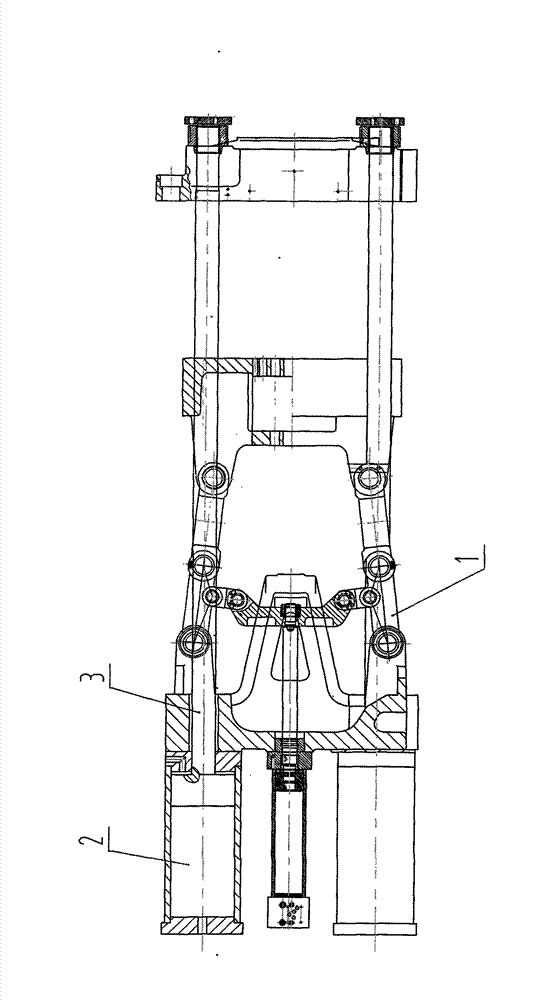
[0011] Such as figure 1 As shown, a compound hydraulic press hinged mold locking mechanism, which includes a traditional formwork machine hinged mold locking assembly (1), a mold adjusting and locking composite oil cylinder body (2), a mold locking pull rod (3), and the mold adjusting lock The mold composite oil cylinder body (2) is fixedly installed on the formwork on one side of the hinged mold lock assembly (1) of the traditional template machine, and one end of the mold lock tie rod (3) is installed on the mold adjustment mold lock composite oil cylinder body (2) In the form of a piston rod, it forms a dynamic fit connection with the mold adjusting and clamping compound oil cylinder body (2), and the other end of the clamping rod (3) is fixed to the template on the other side of the hinge mold clamping assembly (1) of the traditional template machine connect.


PUM


Abstract

The invention discloses a compound hydraulic hinging and locking die mechanism which comprises a conventional template hinging and locking die component, a mold adjusting and mold locking composite oil cylinder body and a mold locking pull rod; by the characteristic that the hinging mechanism is capable of quickly opening and clamping a die, the die can be quickly opened and clamped; the adjustment die and mold locking compound oil cylinder body has a function of finishing direct pressure die locking force at high pressure; and the size of the die locking force is in direct proportion to pressure of hydraulic oil. Due to direct pressure die locking, the parallelism of a template is extremely high; the stress on the mold locking pull rod is completely balanced; die adjustment is also finished by the adjustment die and mold locking compound oil cylinder body; and the mechanism has the high-speed and high-efficiency characteristics of the hinging mechanism and the high-precision characteristic of a hydraulic direct pressing machine or a hydraulic two-plate machine.

Description

Technical field [0001] The invention relates to a compound hydraulic hinge mold locking mechanism for injection molding machinery and die-casting molding machinery. Background technique [0002] The traditional hinged clamping mechanism obtains the clamping force by amplifying the force generated by the straightening of the hinges. The magnitude of this clamping force is difficult to control, and it is also difficult to accurately set the clamping force as required. Because each hinge And the accumulation of processing tolerances of the templates makes the parallelism between the templates clamping the mold not high, resulting in low machine precision. Due to the uneven force, the wear of the machine hinge is aggravated and there is no compensation device, which will further reduce the precision of the machine. The clamping rod The uneven force of the mold clamping rod may cause the breakage of the mold clamping rod. The thread mold adjustment through the mold adjusting scre...

Claims


Application Information

Patent Timeline
Patent Type & Authority Applications(China)
IPC IPC(8): B29C45/67B22D17/26
Inventor 叶廷璧
Owner 叶廷璧
Learn More