
Clamping mechanism of injection molding machine

A technology of injection molding machine and mold clamping, which is applied in the field of mold clamping mechanism of injection molding machine, can solve the problems of low processing precision, uneven clamping force, complex structure, etc., and achieve the effect of high processing precision, balanced force and simple structure

Inactive Publication Date: 2012-08-15
广东顺德立信精密机械有限公司
View PDF3 Cites 0 Cited by
  • Summary
  • Abstract
  • Description
  • Claims
  • Application Information

AI Technical Summary

Problems solved by technology

The structure is complex, the clamping force is unbalanced, and the machining accuracy is low, which needs to be improved

Method used


Image

  • Clamping mechanism of injection molding machine
  • Clamping mechanism of injection molding machine
  • Clamping mechanism of injection molding machine

Examples


Embodiment 1

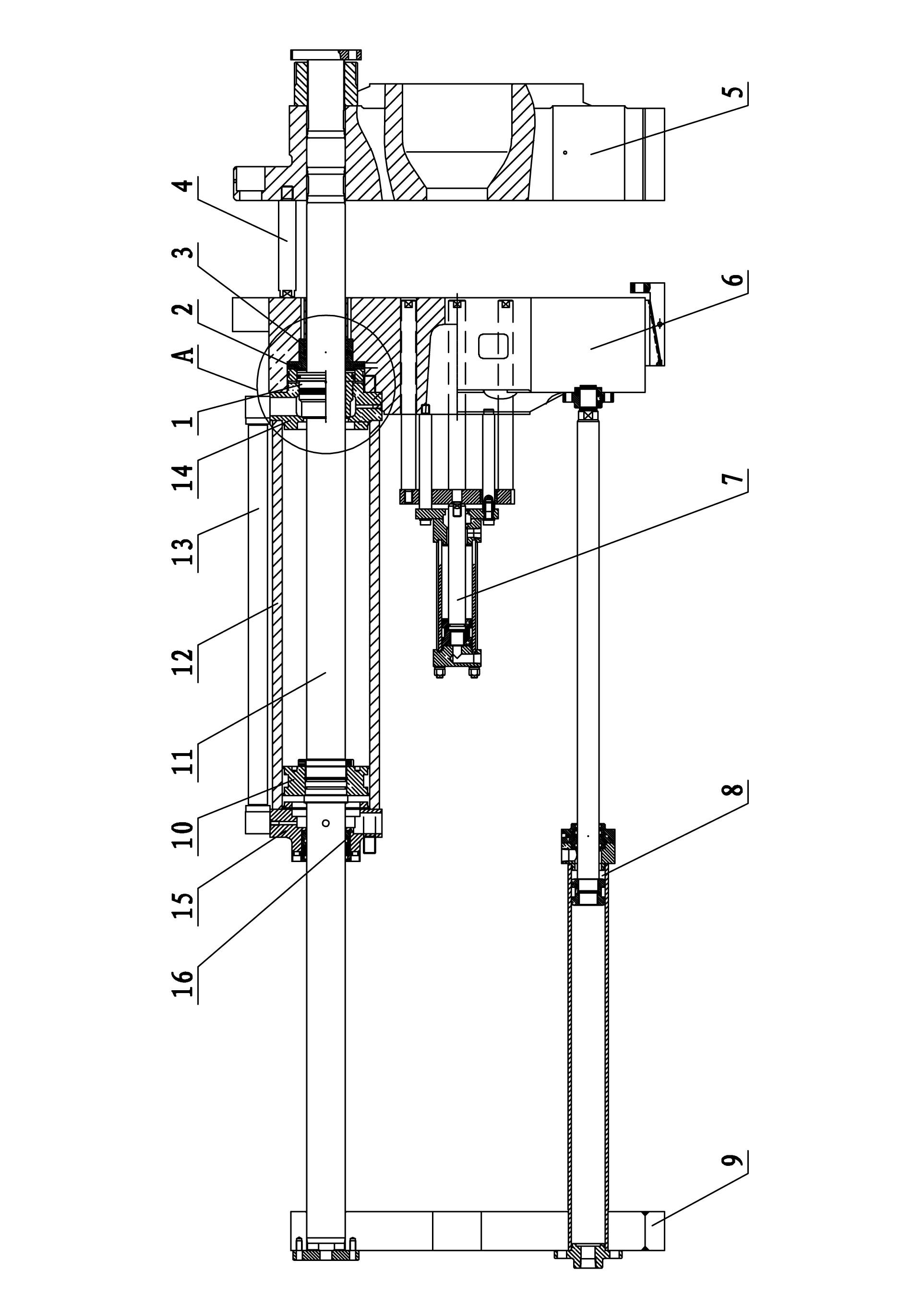
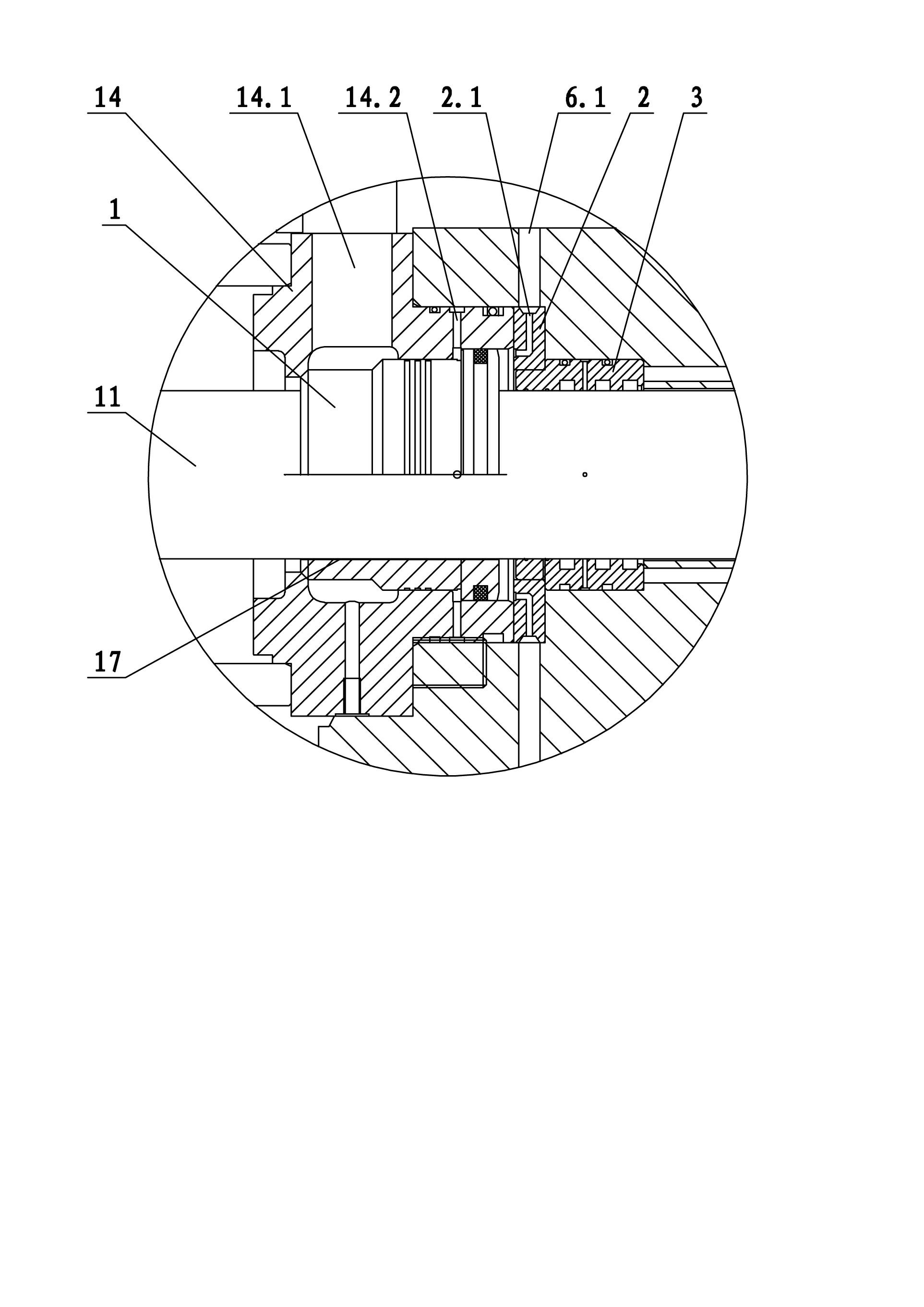
[0026] Embodiment one, such as Figure 1 to Figure 8 As shown, the clamping mechanism of the injection molding machine includes a clamping oil cylinder arranged on the movable template 6, the movable template 6 is slidably arranged on the Gelin column 11, and the front and rear ends of the Gelin column 11 are respectively fixedly connected with the fixed template 5 and the rear Plate 9; the clamping oil cylinder includes a cylinder body 12, a piston 10, a front end cover 14 and a rear end cover 15; the cylinder body 12 is set outside the Corinth column 11, and its front end is fixed to the movable template 6 through the front end cover 14 connection, the rear end is fixedly connected with the rear end cover 15; the piston 10 is set outside the Corinthian column 11 and is located in the cylinder body 12; The front and rear oil passages of the front and rear oil passages are also communicated through the conduction oil pipe 13 outside the cylinder body 12; the front and rear oil...

Embodiment 2

[0038] Embodiment 2 differs from Embodiment 1 in that: the rear plate (support plate) is set in front of the fixed platen, the movable platen is set behind the fixed platen, and the rear plate and the fixed platen are connected by a clamping oil cylinder. The piston rod (Colin column) of the clamping cylinder passes through the fixed template and is connected with the movable template, which is not shown in the figure. For other structures of this clamping cylinder, please refer to Embodiment 1. Compared with the traditional four-cylinder full hydraulic injection molding machine, it has made a major improvement in the overall structure. The clamping cylinder is in front, and the four cylinders are fixed on the fixed platen. The number of moving parts on the moving template is reduced, the energy consumption is low, and the motion inertia is small, thereby effectively reducing a certain amount of energy consumption and improving control accuracy. In addition, the reduction of t...


PUM


Abstract

The invention relates to a clamping mechanism of an injection molding machine, which comprises a clamping cylinder arranged on a movable template, the movable template is slipperily arranged on a Gelin column, and the front and rear ends of the Gelin column are fixedly connected with a fixed template and a rear plate respectively; the clamping cylinder comprises a cylinder body, a piston, a front end cover and a rear end cover; the front end cover and the rear end cover are also respectively provided with a front oil channel and a rear oil channel which are communicated with the inside of the cylinder body, and the front and rear oil channels are communicated through a conducting oil pipe outside the cylinder body; and the front and rear parts of the inside of the front oil channel are slipperily provided with a flow dividing valve body for sealing or opening the front oil channel respectively. The clamping mechanism disclosed by the invention is simple and reasonable in structure, high in mold transferring speed, rapid in clamping, balanced in force, high in machining accuracy, and low in cost.

Description

technical field [0001] The invention relates to the field of injection molding machines and hydraulic equipment, in particular to a clamping mechanism for injection molding machines. Background technique [0002] Chinese patent number CN200520129196.0 disclosed a high-speed and high-precision hydraulic mold clamping device on March 21, 2007, which includes a rear platen, a moving plate, a fixed platen, a tie rod, a mold adjusting cylinder, a tail cover, and a left cover of a high-pressure mold clamping cylinder , high-pressure mold-clamping piston rod, high-pressure mold-closing cylinder right cover, high-speed mold-closing cylinder stuffy cover, high-speed mold-closing cylinder piston rod, high-speed mold-closing cylinder cover; The high-pressure mold-locking cylinder is formed behind the mold piston rod and the right cover of the high-pressure mold-locking cylinder; the high-speed mold-locking cylinder is installed in the holes on both sides of the rear platen, the high-sp...

Claims


Application Information

Patent Timeline
Patent Type & Authority Applications(China)
IPC IPC(8): B29C45/67
Inventor 马廷勇付永涛熊成刚
Owner 广东顺德立信精密机械有限公司
Learn More