Method and device for braking track-bound vehicles driven by induction motors

An induction motor and vehicle technology, applied in the field of rail vehicles

Inactive Publication Date: 2013-05-08
BOMBARDIER TRANSPORTATION GMBH
View PDF6 Cites 3 Cited by
  • Summary
  • Abstract
  • Description
  • Claims
  • Application Information

AI Technical Summary

Problems solved by technology

[0009] In view of the problems mentioned above, it is an object of the present invention to propose an electric ...

Method used


Image

  • Method and device for braking track-bound vehicles driven by induction motors
  • Method and device for braking track-bound vehicles driven by induction motors
  • Method and device for braking track-bound vehicles driven by induction motors

Examples


Embodiment Construction

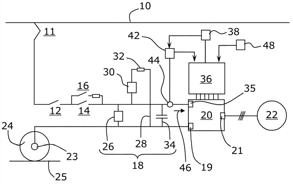
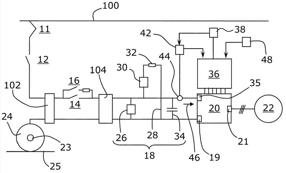
[0041] refer to figure 1 , for rail vehicles, more specifically, a combined electric drive and braking system for rail vehicles powered by a DC catenary line 10 or a transmission rail, comprising a collector 11, a circuit breaker 12, and a separation contactor 14 , the separation contactor 14 is connected in parallel with the charging contactor and the resistance unit 16 . The electric drive and braking system also includes a DC link 18 connected to a DC terminal 19 of a static converter 20 for converting the DC current of the DC link into a three-phase AC current. The static converter 20 has AC terminals 21 connected to an induction motor 22 mechanically linked to an axle 23 of the rail vehicle. The axle 23 is also provided with conventional friction brakes (not shown). The drum 24 of the axle 23 closes the circuit and allows the current to flow back to the supply station via a rail 25 connected to ground.

[0042] The DC link 18 comprises a return unit 26 connected in par...


PUM


Abstract

An electrodynamic brake system for a track-bound vehicle powered by a power line (10, 100) comprises: a current collector (11) for connecting the electrodynamic brake system to the power line (10, 100); a DC link (18) provided with a braking chopper (30), the DC link (18) being powered by the power line (10, 100) through the current collector (11); a static converter (20) operable in a rectifier mode and an inverter mode, the static converter (20) having DC terminals (19) connected to the DC link (18) and AC terminals, wherein electric current flows between the DC link (18) and the DC terminals (19) of the static converter (18) in an inverter direction when the static converter (18) operates in the inverter mode; an induction machine (22) operable as induction motor and in the alternator mode, the induction machine being mechanically linkable to a wheel axle (23) and electrically connected to the AC terminals of the static converter (20); a static converter control unit (36) for controlling the static converter (20) such that the static converter (20) operates in the rectifier mode and the induction machine (22) operates in the alternator mode to feed power back to the DC link (18) in response to an emergency braking signal, and an electrodynamic brake supervision unit (36) for shutting off the static converter (20) to isolate the induction machine (22) from the DC link (18) upon detection of a motoring condition during emergency braking.

Description

technical field [0001] The invention relates to rail vehicles driven by induction motors and powered by overhead lines or third rails. The invention relates particularly, but not exclusively, to a multiple-unit rail vehicle comprising a multi-section vehicle driven by induction motors distributed over the length of the vehicle. The invention relates more particularly to an actuation system suitable for such a vehicle, in particular an emergency braking system, and also to a corresponding braking method. Background technique [0002] Traditionally, rail vehicles are provided with several different braking devices, such as mechanical or electric brakes. Mechanical brakes are usually pneumatic and convert the kinetic energy of the rail vehicle into heat through friction. Electric brakes convert the vehicle's kinetic energy into electrical energy, which can be dissipated as heat in a rheostat (resistive braking) or fed back into a power line such as an overhead catenary or pow...

Claims


Application Information

Patent Timeline
IPC IPC(8): B60L7/00B60L3/00
CPCB60L2200/26B60L7/16B60L9/22Y02T10/648B60L3/0076Y02T10/64B60L7/10B61H11/02
Inventor 科林·博雷斯安德斯·罗兴马丁·童格詹姆士·威尔逊詹姆士·巴伯斯特芬·波拉姆博尔
Owner BOMBARDIER TRANSPORTATION GMBH
Why Eureka
Try Eureka