Obstacle remover components and EMUs

A technology of obstacle remover and EMU, which is applied to railway car body components, railway vehicle wheel guards/buffers, transportation and packaging, etc., which can solve the problems that airflow cannot flow away and increase the resistance of tail cars, etc.

Active Publication Date: 2015-08-26
CRRC TANGSHAN CO LTD
View PDF6 Cites 1 Cited by
  • Summary
  • Abstract
  • Description
  • Claims
  • Application Information

AI Technical Summary

Problems solved by technology

[0005] There are at least the following problems in the prior art: the head car and the tail car of the EMU are fixedly installed with an obstacle remover. For the tail car of the EMU in operation, the installation of the obstacle remover prevents the airflow at the bottom of the tail car from quickly The nose cone of the car flows away, generating more eddy currents, which increases the resistance of the rear car

Method used


Image

  • Obstacle remover components and EMUs
  • Obstacle remover components and EMUs
  • Obstacle remover components and EMUs

Examples


Embodiment Construction

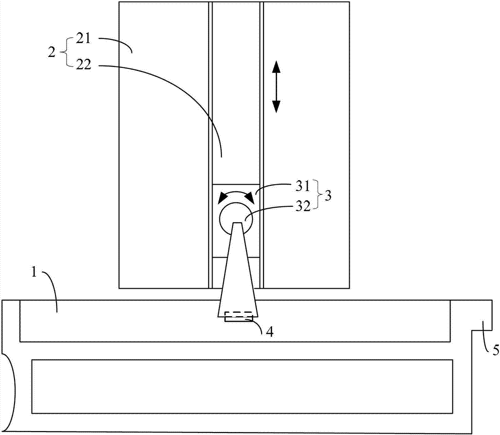
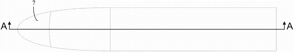
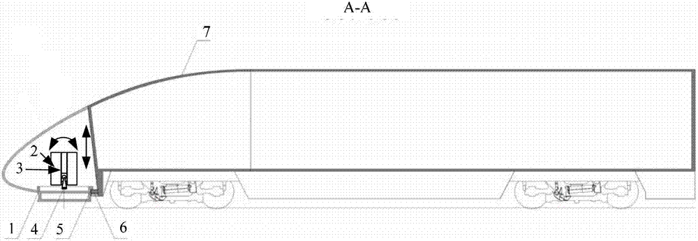
[0032] figure 1 It is a schematic structural diagram of the obstacle remover assembly provided by Embodiment 1 of the present invention, figure 2 for figure 1 The schematic diagram of the top view of the block remover assembly used on the EMU, image 3 for figure 2 A-A sectional view of, Figure 4 for image 3 The partially enlarged schematic diagram of Figure 5 for Figure 4 The schematic diagram after the obstacle remover on the EMU is raised, Figure 6 for Figure 5 The schematic diagram after the obstacle remover on the EMU is rotated, Figure 7 for figure 2 The schematic diagram of looking up, Figure 8 for Figure 7 A partially enlarged schematic diagram.

[0033] see Figure 1-Figure 8 , Embodiment 1 of the present invention provides an assembly of an obstacle remover 1, which includes an obstacle remover 1 and an installation part, the installation part includes a fixed part 2 and a moving part 3, and the fixed part 2 is used to be fixed on the head of...


PUM


Abstract

The invention provides a pilot assembly and a motor train unit. The pilot assembly comprises a pilot and a mounting component, wherein the mounting component comprises a fixed component and a moving component, the fixed component is used for being fixed on a head car or a tail car of the motor train unit, the moving component is movably arranged on the fixed component, the pilot is fixed on the moving component, and the moving component can move along the height direction of the motor train unit and can turn around the direction parallel to the axle of the motor train unit. According to the pilot component, due to the fact that the pilot can be hidden, extra power does not need consuming, and simple measures are adopted, so that trail eddy resistance of the streamline motor train unit can be reduced. Thus, the running resistance of the whole motor train unit is reduced, and energy is saved.

Description

technical field [0001] The invention relates to mechanical technology, in particular to an obstacle remover assembly and an EMU. Background technique [0002] As the speed of the EMU continues to increase, the running resistance of the EMU also increases significantly. When the EMU speed reaches 200km / h, the air resistance accounts for about 70% of the total running resistance; when the EMU speed reaches 300km / h, the air resistance accounts for about 85% of the total running resistance. Most of the energy consumed in the operation of EMUs is used to overcome air resistance. [0003] When the EMU is driving from the starting station to the terminal station, the head car is in front and the tail car is behind; Among them, the shape of the head car is the same as that of the tail car. [0004] For the safety of the EMU operation, it is necessary to install obstacle removers on the head car and the tail car to remove the obstacles directly in front of the EMU, and prevent the...

Claims


Application Information

Patent Timeline
Patent Type & Authority Patents(China)
IPC IPC(8): B61F19/06
Inventor 刘慧军黄烈威孙加平刘晋刘志昆
Owner CRRC TANGSHAN CO LTD
Why Eureka
Try Eureka