Railway vehicle telescopic head and railway vehicle
What is Al technical title?
Al technical title is built by PatSnap Al team. It summarizes the technical point description of the patent document.
A technology for rail vehicles and locomotives, applied in the field of rail vehicles, can solve the problems of loose tail scrolls and large aerodynamic resistance of fast-back car shape, and achieve the effects of reducing rear resistance, eddy current resistance, and reducing running resistance.
Active Publication Date: 2015-05-20
CRRC TANGSHAN CO LTD
View PDF6 Cites 0 Cited by
Summary
Abstract
Description
Claims
Application Information
AI Technical Summary
This helps you quickly interpret patents by identifying the three key elements:
Problems solved by technology
Method used
Benefits of technology
Problems solved by technology
[0005] "Vehicles and Power Technology" 2005, No. 3, P12; Authors: Kang Ning, Qiao Junping "Research on the influence of wake vortex characteristics on the aerodynamic drag of cars" used the commercial CFD software STAR-CD to study the external flow fields of two car models According to the numerical simulation, according to the velocity vector diagram and the three-dimensional streamline diagram, it can be clearly seen that at the rear of the car, the airflow has separated, forming two pairs of upper and lower vortices with a larger size, and finally merged together and extended to the wake; The tail vortex of the hatchback model is looser and dissipates faster at the rear of the body, while the tail vortex of the fastback model is tighter. Extended, it exists within a long distance at the rear of the car body. It is precisely because of the strong wake vortex that the aerodynamic resistance of the fastback car is relatively large.
Method used
Image
Click on the blue label to locate the original text in one second.
Reading with bidirectional positioning of images and text.
Examples
Embodiment Construction
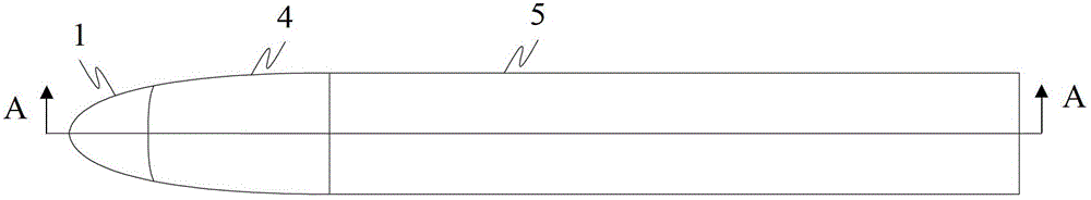
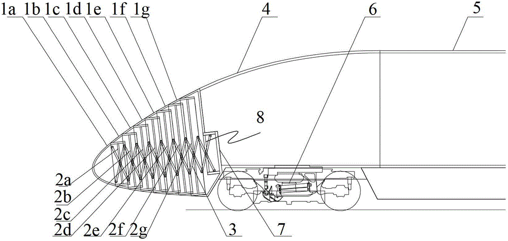
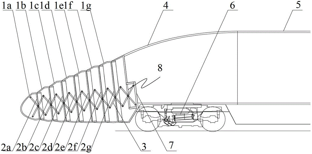
[0019] figure 1 A schematic diagram of a rail vehicle provided by an embodiment of the present invention; figure 2 for figure 1 A sectional view of the front end along A-A in the center; image 3 for figure 1 A cross-sectional view of the rear end of the car along the middle line A-A; Figure 4 It is a partial enlarged view of the nose cone of the car; Figure 5 for Figure 4 right view of Figure 6 It is a schematic diagram of the assembled state of the rail vehicle; Figure 7 It is a schematic diagram of a rail vehicle driving from station X to station Y; Figure 8 is a schematic diagram of a rail vehicle driving from station Y to station X; for example Figure 1-8 As shown, the embodiment of the present invention provides a telescopic locomotive for rail vehicles. The locomotive is composed of a locomotive front end 1 and a locomotive body 4 that are rotatably connected. Shaped segment body, the telescopic frame and at least one connecting rod 20 arranged in the t...
PUM
Abstract
A telescoping railway vehicle head and railway vehicle, the head comprising: a telescoping front end (1) of the head, a head body (4) behind, and an internal telescoping frame (3). The telescoping front end (1) of the head comprises multiple centipede-like unit sections (1a, 1b, 1c, 1d, 1e, 1f, 1g) connected in a head-to-tail manner and corresponding connecting rods (2a, 2b, 2c, 2d, 2e, 2f, 2g) fixedly disposed in the unit sections (1a, 1b, 1c, 1d, 1e, 1f, 1g). The telescoping frame (3) comprises several swing rods (3a) and swing shafts (3b), the swing rods (3a) are rotationally connected in a head-to-tail manner via the swing shafts (3b) to form a telescoping diamond-shaped frame in the longitudinal direction of the head. The telescoping frame (3) drives the connecting rods (2a, 2b, 2c, 2d, 2e, 2f, 2g) together with the centipede-like unit sections (1a, 1b, 1c, 1d, 1e, 1f, 1g) to shift back and forth in the longitudinal direction of the head, thus changing the aerodynamic resistance of the head by driving the telescoping front end (1) of the head. A railway vehicle comprises a vehicle body, and telescoping heads connected to the front and back of the vehicle body. The combined aerodynamic resistance of the front and the back is changed by driving the telescoping front end (1) of the head at the front and the back of the vehicle body.
Description
technical field [0001] The invention relates to rail vehicle technology, in particular to a rail vehicle retractable head and a rail vehicle. Background technique [0002] With the continuous improvement of the speed of rail vehicles, especially the EMU, the resistance of the EMU will increase significantly. When the speed of the EMU reaches 200km / h, the air resistance accounts for about 70% of the total running resistance. When the speed of the EMU reaches 300km / h h, the air resistance accounts for about 85% of the total running resistance, and most of the energy consumed in the operation of the EMU is used to overcome the air resistance. [0003] The research shows that the relationship between the aerodynamic performance and the main shape parameters of the head shape, including the length of the streamlined head, the variation of the main shape of the longitudinal section, the variation of the main shape of the horizontal plane, and the maximum cross-sectional area; the ...
Claims
Application Information
Patent Timeline
Application Date:The date an application was filed.
Publication Date:The date a patent or application was officially published.
First Publication Date:The earliest publication date of a patent with the same application number.
Issue Date:Publication date of the patent grant document.
PCT Entry Date:The Entry date of PCT National Phase.
Estimated Expiry Date:The statutory expiry date of a patent right according to the Patent Law, and it is the longest term of protection that the patent right can achieve without the termination of the patent right due to other reasons(Term extension factor has been taken into account ).
Invalid Date:Actual expiry date is based on effective date or publication date of legal transaction data of invalid patent.