Countercurrent-tank-type calcining furnace

A calciner and countercurrent tank technology, which is applied in the field of countercurrent tank calciners, can solve problems such as large energy consumption, and achieve the effects of reducing exhaust gas temperature, small pressure loss, and increasing calcination temperature.

Active Publication Date: 2013-05-08
SHENYANG ALUMINIUM MAGNESIUM INSTITUTE
View PDF4 Cites 16 Cited by
  • Summary
  • Abstract
  • Description
  • Claims
  • Application Information

AI Technical Summary

Problems solved by technology

However, the energy consumption is relatively large, so it is imperative to invent a calcination equipment that reduces consumption and increases efficiency.

Method used


Image

  • Countercurrent-tank-type calcining furnace
  • Countercurrent-tank-type calcining furnace

Examples


Embodiment Construction

[0014] The present invention will be further described in detail below in conjunction with the examples, but the protection scope of the present invention is not limited by the examples.

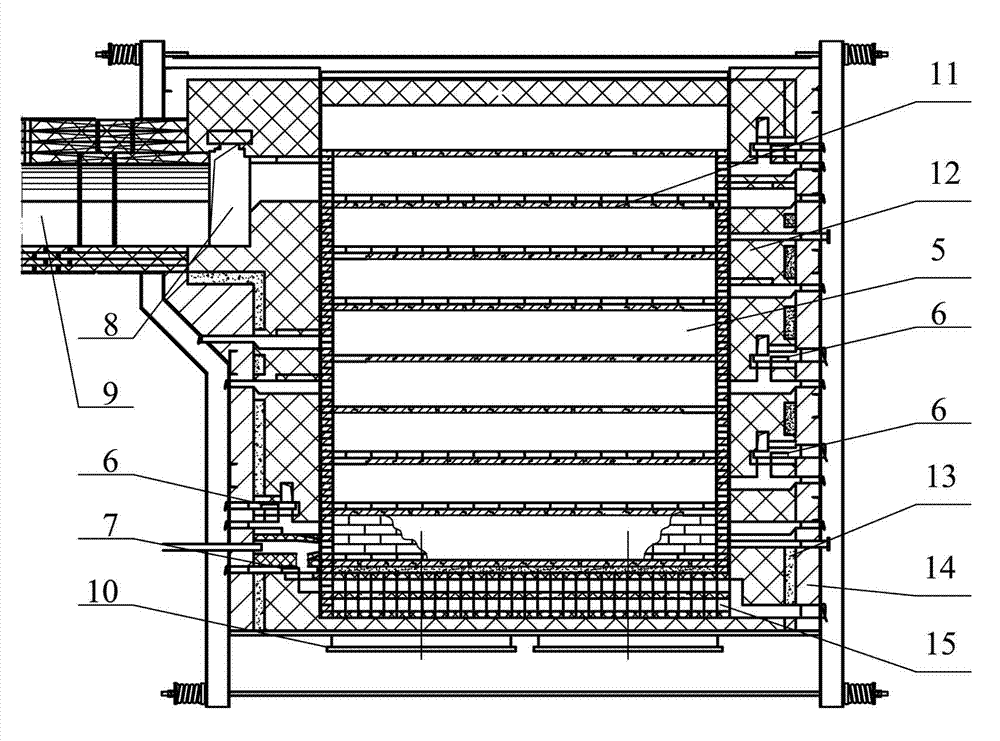
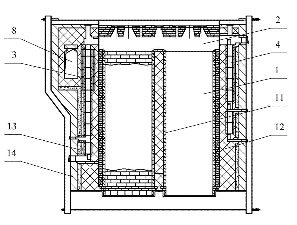
[0015] As shown in the figure, the countercurrent tank type calciner of the present invention includes a material tank 1, a fire channel 5 arranged on both sides of the material tank, a front wall and a rear wall, and the top of the material tank 1 is provided with a volatile matter concentration channel 2, and inside the front wall There is a volatile content vertical channel 3 on the front wall, and a rear wall volatile content vertical channel 4 is arranged in the rear wall. There is a volatile part pull plate 6, and the volatile part vertical channel 4 on the back wall is connected to the volatile part concentration channel 2 and the penultimate layer of the fire channel 5 and the middle part of the fire channel 5, and the penultimate layer of the fire channel 5 and the middle part of the...


PUM


Abstract

The invention relates to a countercurrent-tank-type calcining furnace comprising material tanks, fire paths provided on two sides of the material tanks, a front wall, and a back wall. A volatile content centralization channel is arranged above the material tanks. A front wall volatile content vertical channel is arranged in the front wall. A back wall volatile content vertical channel is arranged in the back wall. The front wall volatile content vertical channel communicates the volatile content centralization channel and bottom-layer fire paths. Volatile content drawing boards are arranged at the inlet ports of the bottom-layer fire paths. The back wall volatile content vertical channel communicates the volatile content centralization channel and last-but-two-layer fire paths and middle-part fire paths. Volatile content drawing boards are arranged at inlet ports of the last-but-two-layer fire paths and the middle-part fire paths. A preheated air channel is arranged below the bottom-layer fire paths. A preheated air drawing board is arranged at the inlet port of the preheated air channel. The preheated air channel and the bottom-layer fire paths are communicated at the front wall. First-layer fire paths are communicated with a flue. A cooling water jacket is arranged below the material tanks. With the furnace provided by the invention, maximal calcining temperature can be increased, such that product quality can be improved.

Description

technical field [0001] The invention relates to a pot-type calciner, in particular to a counter-current pot-type calciner for producing aluminum anodes, cathodes, electrodes and carbon graphitized materials in the carbon industry. Background technique [0002] With the continuous increase of production capacity of modern carbon enterprises, especially large-scale electrolytic aluminum plants and electrode plants, while the production capacity of carbon products continues to increase, the requirements for the quality of calcined coke are becoming more and more stringent. Now the electrolytic cell current is gradually increasing, the anode current density is increasing, and the degree of automation is gradually increasing, so the quality requirements for carbon anodes are also gradually increasing. Calcination is the first process of anode products, and the quality of calcined coke largely determines the quality of anodes. At present, the commonly used calcination equipment ...

Claims


Application Information

Patent Timeline
Patent Type & Authority Applications(China)
IPC IPC(8): C01B31/02
CPCF23L15/00F27B14/00C01B31/02F23G5/00F27B14/14Y02E20/34Y02P20/129
Inventor 周善红孙毅崔银河刘朝东许海飞王敏许开伟吕博李晓坤李鹏
Owner SHENYANG ALUMINIUM MAGNESIUM INSTITUTE
Why Eureka
Try Eureka