

Suspension bridge anti-skidding cable clamp
An anti-slip, suspension bridge technology, applied in bridges, bridge parts, bridge construction and other directions, can solve the problems of increased difficulty in manufacturing cable clips, difficult installation and operation of cable clips, and increased manufacturing costs of cable clips, and achieves control of manufacturing costs and locks. Tight friction can increase and reduce the effect of labor intensity
- Summary
- Abstract
- Description
- Claims
- Application Information
AI Technical Summary
Problems solved by technology
Method used
Image

Examples
Embodiment 1
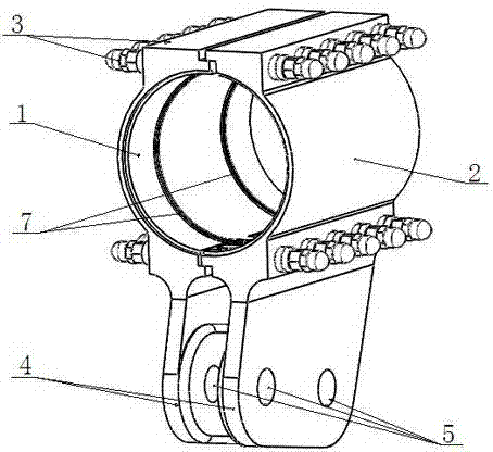
[0016] see figure 1 : the present invention comprises the first semi-annular body 1 and the second semi-annular body 2 that cooperate together with left and right sides, the two ends of the annular profile of the first semi-annular body 1 and the second semi-annular body 2 are provided with connecting steps, the second A plurality of bolt holes corresponding to each other are provided on the connecting steps of the half-ring body 1 and the second half-ring body 2, and the first half-ring body 1 and the second half-ring body 2 are connected together by a plurality of high-strength bolts 3, Washers and nuts are assembled on the high-strength bolts 3 . Connecting lugs 4 extending downward are respectively provided at the lower end connecting steps of the first half-ring body 1 and the second half-ring body 2. The pin hole 5. The inner walls of the first semi-annular body 1 and the second semi-annular body 2 are respectively processed with anti-slip structures 7 by cutting and g...
Embodiment 2
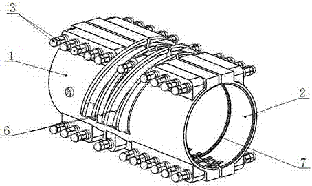
[0018] see figure 2 : the present invention comprises the first semi-annular body 1 and the second semi-annular body 2 that cooperate together with left and right sides, the two ends of the annular profile of the first semi-annular body 1 and the second semi-annular body 2 are provided with connecting steps, the second A plurality of bolt holes corresponding to each other are provided on the connecting steps of the half-ring body 1 and the second half-ring body 2, and the first half-ring body 1 and the second half-ring body 2 are connected together by a plurality of high-strength bolts 3, Washers and nuts are assembled on the high-strength bolts 3 . On the upper half of the outer wall of the first semi-annular body 1 and the second semi-annular body 2, a plurality of straddle grooves 6 corresponding to each other are provided. sling. The inner walls of the first semi-annular body 1 and the second semi-annular body 2 are respectively processed with anti-slip structures 7 by ...
Embodiment 3
[0020] The present invention comprises the first semi-annular body and the second semi-annular body that fit together above and below, the first semi-annular body and the second semi-annular body are molded by casting respectively, the first semi-annular body and the second semi-annular body There are connecting steps at both ends of the ring profile, and a plurality of bolt holes corresponding to each other are provided on the connecting steps of the first half-ring body and the second half-ring body, and the first half-ring body and the second half-ring body pass through multiple high-strength Bolted together, high strength bolts are fitted with washers and nuts. On the outer wall of the first semi-annular body, a plurality of straddle grooves with a certain inclined angle are arranged, and the straddle grooves are used for connecting slings. The inner walls of the first semi-annular body and the second semi-annular body are respectively provided with an anti-slip structure ...
PUM
 Abstract
Description
Claims
Application Information