Installation structure of seamless installation clamping key and outdoor floor
What is Al technical title?
Al technical title is built by PatSnap Al team. It summarizes the technical point description of the patent document.
A technology of installation structure and installation card, applied in the direction of building structure, floor, building, etc., can solve the problems of unsightly, upturned plate, installation error, etc., and achieve the effect of simple installation process, reasonable design and simple structure
Active Publication Date: 2013-05-08
ANHUI SENTAI WPC GRP CO LTD
View PDF6 Cites 5 Cited by
Summary
Abstract
Description
Claims
Application Information
AI Technical Summary
This helps you quickly interpret patents by identifying the three key elements:
Problems solved by technology
Method used
Benefits of technology
Problems solved by technology
In actual use, when paving the floor outdoors, self-tapping nails are generally used to directly nail the composite floor to the ground, or simply use cement to pave the composite floor on the ground, and then use plastic key The connection is fixed, but the wood-plastic or bamboo-plastic composite floor itself has the property of expansion, and it will expand and contract when the temperature changes. Therefore, there should be some space between adjacent wood-plastic or bamboo-plastic floors during installation There are gaps, otherwise there is no room for movement, unreasonable construction or installation errors will cause the board to warp and arch
Moreover, because the plastic key is easy to age, become brittle and break, the vibration resistance and impact resistance are poor, and it is easy to cause deformation and translocation, which is neither beautiful nor safe.
Method used
Image
Click on the blue label to locate the original text in one second.
Reading with bidirectional positioning of images and text.
Examples
Embodiment Construction
[0021] In order to make the technical means, creative features, goals and effects achieved by the present invention easy to understand, the present invention will be further described below in conjunction with specific illustrations.
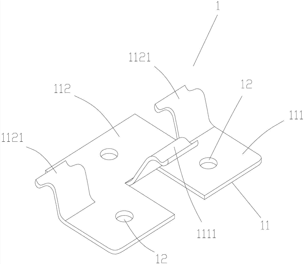
[0022] Such as figure 1 As shown, a seamless installation card key and an outdoor floor installation structure, the metal card key 1 includes a connecting plate 11, the connecting plate 11 is a square structure, and the connecting plate 11 is bounded on the connecting plate 11 with the center line of the connecting plate 11 as the boundary line. It is divided into a first clamping part 112 and a second clamping part 111, and on both sides of the first clamping part 112, the center line of the connecting plate 11 is used as a fulcrum to bend the two sides of the first clamping part 112 upward to form two first claws 1121, At the middle position of the second clamping part 111, the middle part of the second clamping part 111 is bent upward to form...
PUM
Abstract
The invention discloses an installation structure of a metal clamping key and a floor, and relates to the technical field of connecting pieces for floor pavement. The metal clamping key comprises a connecting plate. The installation structure is characterized in that the connecting plate is in a square structure, the connecting plate is divided into a first clamping portion and a second clamping portion with a center line of the connecting plate as a boundary line, two edges of the first clamping portion are bent upward to form two first clamping claws at the positions of the two edges of the first clamping portion and with the center line of the connecting plate as a supporting point, the middle part of the second clamping portion is bent upward to form a second clamping claw at the middle position of the second clamping portion and with the center line of the connecting plate as a supporting point, and free ends of the upper end portions of the first clamping claws and the second clamping claw are roughly in a V-shaped structure. The installation structure is simple in structure and reasonable in design, and changes the connecting method that a tenon and a mortise are adopted in a traditional floor, installation process is simpler, matching between the clamping key and the floor is close, gas between two floors is small after the floors are assembled, the fact that the clamping key cannot be corroded is well guaranteed, and the installation structure is not prone to deformation, strong in bearing capacity and attractive in appearance.
Description
technical field [0001] The invention relates to the technical field of floor paving, in particular to a seamless installation key and an outdoor floor installation structure. Background technique [0002] Wood-plastic composite materials have been widely used in clapboards, wall panels, planks, decorative panels, fences, stair handrails, building templates, building doors and windows, outdoor roof tiles, and automotive interior parts since they were first successfully developed in western developed countries. ; Combination pallets, packing boxes, storage boxes, flower boxes, storage racks for packaging and logistics; highway noise partitions, seaside road boards, railway sleepers; can also be used as decorative frames, ship cockpit partitions, office partitions, outdoor Open-air tables and benches, movable shelves, etc. The materials under development include folding boards, shutters, indoor roof panels, student desks and chairs, etc. This new technology has just started in...
Claims
Application Information
Patent Timeline
Application Date:The date an application was filed.
Publication Date:The date a patent or application was officially published.
First Publication Date:The earliest publication date of a patent with the same application number.
Issue Date:Publication date of the patent grant document.
PCT Entry Date:The Entry date of PCT National Phase.
Estimated Expiry Date:The statutory expiry date of a patent right according to the Patent Law, and it is the longest term of protection that the patent right can achieve without the termination of the patent right due to other reasons(Term extension factor has been taken into account ).
Invalid Date:Actual expiry date is based on effective date or publication date of legal transaction data of invalid patent.