Plate heat exchanger

A technology of plate heat exchangers and plates, applied in the direction of heat exchanger types, heat exchanger shells, indirect heat exchangers, etc., can solve the problem of reducing the overall utilization rate of plates 1, making it difficult to ensure smooth circulation, and unable to obtain effective Reduction and other problems, to solve the problem of uneven gas-liquid distribution, shape and application restrictions, and improve the effect of fluid distribution

Active Publication Date: 2015-11-25
ZHEJIANG SANHUA AUTOMOTIVE COMPONENTS CO LTD
View PDF10 Cites 1 Cited by
  • Summary
  • Abstract
  • Description
  • Claims
  • Application Information

AI Technical Summary

Problems solved by technology

[0007] First, by figure 1 It can be seen that in order to realize the distribution of the two fluids between the plates 1 without interfering with each other, the plate 1 needs to be provided with at least four corner holes to form a fluid channel (one kind of fluid needs to be provided with two corner holes). Edge flow or diagonal flow, but for these two flow modes, the fluid between plate 1 cannot be evenly distributed in the area of ​​plate 1 near the two corner holes where the retaining ring is set, this area cannot be effectively used, and still exists The problem of uneven heat transfer and low heat transfer efficiency, when there are more than two types of heat transfer fluid, the number of corner holes is more, the above problems are more significant; moreover, each fluid needs to be provided with two corner holes, at least four corner holes Occupies a larger area of ​​the plate 1, correspondingly reduces the overall utilization of the plate 1, and at the same time, the arrangement of four corner holes in the four corners of the plate 1 also limits the design, shape and related applications of the plate heat exchanger
[0008] Second, the channel composed of corner holes is difficult to ensure the smoothness of circulation. The pressure drop of the fluid flowing in this channel is relatively large, which accounts for a part of the pressure drop of the plate heat exchanger. Due to the limitation of the corner hole structure, the pressure drop is relatively large The problem cannot be effectively reduced, and it cannot be adapted to the needs of different working conditions

Method used


Image

  • Plate heat exchanger
  • Plate heat exchanger
  • Plate heat exchanger

Examples


Embodiment Construction

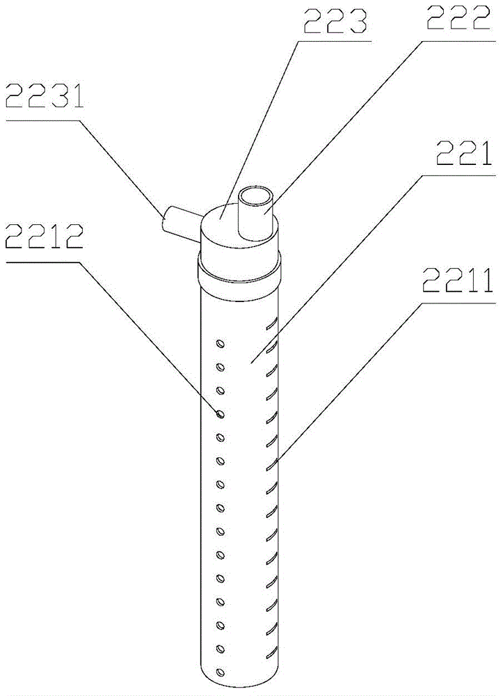
[0044] The core of the present invention is to provide a plate heat exchanger, the plates of the plate heat exchanger are provided with mixing through holes and a fluid distributor, so that the fluid can flow evenly between the plates and improve the utilization rate of the plates and heat transfer efficiency.

[0045] In order to make those skilled in the art better understand the technical solutions of the present invention, the present invention will be further described in detail below with reference to the accompanying drawings and specific embodiments.

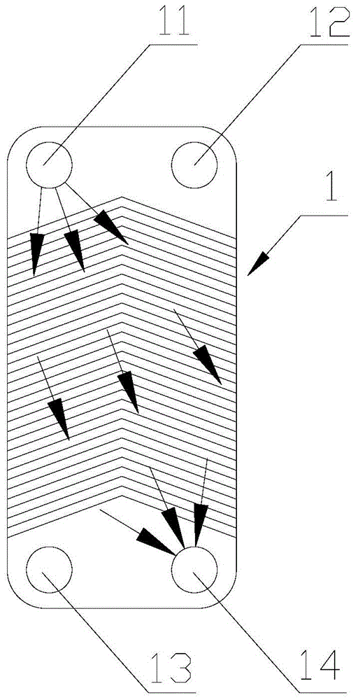
[0046] The plate heat exchanger provided by this specific embodiment includes stacked plates, and an inter-plate flow channel is formed between the plates. Usually, a pattern is machined on the surface of the plate to form an inter-plate flow channel. The inter-flow channel facilitates the uniform flow of fluid between the plates.

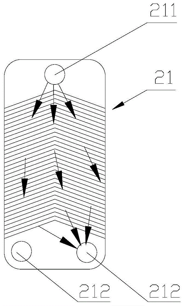
[0047] Please refer to figure 2 , figure 2 It is a schematic diagram of the first st...


PUM


Abstract

The invention discloses a plate heat exchanger. The plate heat exchanger comprises plate sheets (21) which are stacked; interplate flow channels are formed among the plate sheets (21); the plate heat exchanger also comprises a flow distributor (22) which is communicated with the interplate flow channels and comprises at least two pipelines which are arranged in parallel; all the interplate flow channels are communicated with an independent pipeline; and adjacent interplate flow channels are communicated with different pipelines of the flow distributor respectively. The flow distributor of the plate heat exchanger at least comprises two pipelines, so that the number of single flowing holes on the plate sheets can be reduced; therefore, the heat exchange efficiency of fluid and the utilization rate of the plate sheets can be improved; an area where the fluid can flow is enlarged, and the fluid can be distributed more uniformly among the plates; and moreover, according to the plate heat exchanger with the structure, pressure drop is easy to adjust, and the fluid distribution condition under the working condition of phase change can be changed.

Description

technical field [0001] The invention relates to the technical field of heat exchange, in particular to a plate heat exchanger. Background technique [0002] The plate heat exchanger has the characteristics of compactness and high efficiency, and is generally used for heat exchange between two fluids, such as liquid-liquid and liquid-gas heat exchange modes, and can also be used in conditions with fluid phase change, such as Condenser, Evaporator. [0003] Please refer to figure 1 , figure 1 It is a schematic diagram of the plate of a typical plate heat exchanger. [0004] The plate heat exchanger generally fixes several pressed plates 1 together in some way, such as brazing, frame fixing, etc., so that the two fluids, cold and hot, pass alternately between the plates to achieve heat exchange, that is, flow in the heat exchanger. The fluids on both sides of a plate 1 are high temperature fluid and low temperature fluid respectively. figure 1 The plate 1 is suitable for a...

Claims


Application Information

Patent Timeline
Patent Type & Authority Patents(China)
IPC IPC(8): F28D9/00F28F9/22F28F3/08
Inventor 王耀光
Owner ZHEJIANG SANHUA AUTOMOTIVE COMPONENTS CO LTD
Why Eureka
Try Eureka