Coil component and manufacturing method thereof

A manufacturing method and coil component technology, applied in coil manufacturing, transformer/inductor coil/winding/connection, electrical components, etc., can solve the problems of increased manufacturing procedures, increased defect rate, and difficult reduction of production costs, and achieve heavy The effect of increasing the overlapping area, improving durability and service life, and not easy to fall off or break

Inactive Publication Date: 2013-05-08
TMP INT CORP
View PDF0 Cites 2 Cited by
  • Summary
  • Abstract
  • Description
  • Claims
  • Application Information

AI Technical Summary

Problems solved by technology

However, this method requires additional manufacturing of electrode wires and welding, the entire manufacturing process needs to be increased, and the production cost is not easy to reduce
Moreover, due to welding on the coil, there will be solder joints, which greatly increases the chance of forming a defective rate in the manufacturing process, and the quality is more difficult to control.

Method used


Image

  • Coil component and manufacturing method thereof
  • Coil component and manufacturing method thereof
  • Coil component and manufacturing method thereof

Examples


Embodiment Construction

[0045] A coil assembly and a manufacturing method thereof according to preferred embodiments of the present invention will be described below with reference to related drawings, wherein the same components will be described with the same reference numerals.

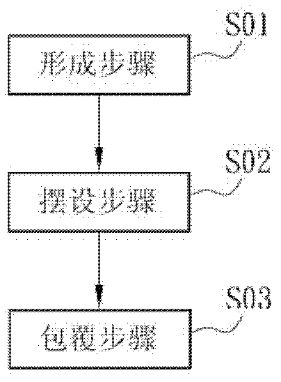
[0046] figure 2 It is a flow chart of a manufacturing method of a coil assembly in a preferred embodiment of the present invention.

[0047] Such as figure 2 As shown, the production method includes the following steps:

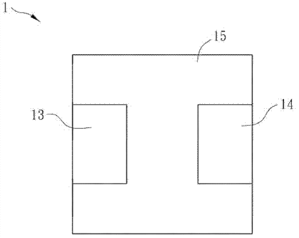
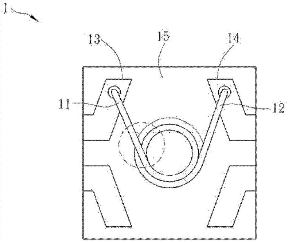
[0048] Step S01: a forming step, forming a first coil and a second coil connected to each other, the first coil is located inside the second coil;

[0049] Step S02: an arranging step, arranging a tail end segment of the first stitch on the last segment along the outline of a last segment of the second stitch; and

[0050] Step S03: a covering step, covering the first coil and the second coil.

[0051] The first coil and the second coil are formed by the same wire. The inner layer of the wire is pr...


PUM


Abstract

A manufacturing method for a coil component includes a forming step: forming a first coil and a second coil which are mutually connected, wherein the first coil is positioned on the inner side of the second coil; an arranging step: arranging a tail-end coil section of the first coil on a tail-circle coil section of the second coil along the outline of the tail-circle coil section; and a coating step: coating the first coil and the second coil. By above manufacturing method, overlapping area of the tail-end coil section of the inner coil and the outer coil is enlarged, insulating layers of the coils are enabled to be less prone to falling off or being damaged, thus, durability of the coil component is improved, and service life of the coil component is prolonged.

Description

technical field [0001] The present invention relates to a coil and a manufacturing method thereof, in particular to a coil component and a manufacturing method thereof. Background technique [0002] Coil assemblies are fundamental electronic components with a wide range of uses, ranging from inductors to solenoid windings in transformers or motors. [0003] Figure 1A is a top view of a coil assembly 1, Figure 1B is the internal perspective view of the coil assembly 1, as Figure 1A and Figure 1B As shown, the coil assembly 1 has inner and outer layers of coils 11 , 12 , two electrode pins 13 , 14 and a covering body 15 . Wherein the coil 11 is located inside the coil 12 and the coils 11, 12 are connected to each other, and the tail ends of the coils 11, 12 are respectively used as contacts for electrical connection for connecting with the electrode pins 13, 14, and the covering body 15 is Coils 11, 12 are covered. [0004] The coils 11 and 12 are wound in a three-dime...

Claims


Application Information

Patent Timeline
Patent Type & Authority Applications(China)
IPC IPC(8): H01F27/28H01F41/06H01F41/071
Inventor 陈明琦
Owner TMP INT CORP
Why Eureka
Try Eureka