Method and device of broadband bundle beam current detecting

A broadband, beam technology, used in measurement devices, radiation measurement, X/γ/cosmic radiation measurement, etc.

Active Publication Date: 2013-05-08
BEIJING SHUOKE ZHONGKEXIN ELECTRONICS EQUIP CO LTD
View PDF4 Cites 8 Cited by
  • Summary
  • Abstract
  • Description
  • Claims
  • Application Information

AI Technical Summary

Problems solved by technology

[0005] The measurement of uniformity is also a complex process

Method used


Image

  • Method and device of broadband bundle beam current detecting
  • Method and device of broadband bundle beam current detecting
  • Method and device of broadband bundle beam current detecting

Examples


Embodiment Construction

[0028] The present invention will be described in further detail below in conjunction with specific examples, but not as a limitation to the patent of the present invention.

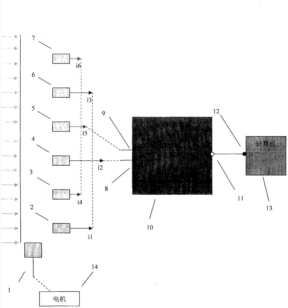
[0029] First, the signal output terminal (11) is selected to communicate with the signal input terminal (8), and the motor (14) starts to drive the movement of the Faraday cup (1). Before moving the Faraday cup (1) to block any beam measuring cup, record the beam current measured by the (2), (4), and (6) beam measuring Faraday cups connected in parallel to the acquisition system as: IA=0.0649mA. When the measuring beam Faraday cup (2) is completely blocked by the moving Faraday cup (1), the measured total beam current value is I23=0.0460mA. When the measuring beam Faraday cup (4) is completely blocked by the moving Faraday cup (1), the measured total beam current value is I13=0.0439mA. When the measuring beam Faraday cup (6) is completely blocked by the moving Faraday cup (1), the measured total beam cu...


PUM


Abstract

The invention states a method and a device of broadband bundle beam current detecting. The device comprises a movable faraday cup (1), a bundle detecting faraday cup (2), a bundle detecting faraday cup (3), a bundle detecting faraday cup (4), a bundle detecting faraday cup (5), a bundle detecting faraday cup (6) and a bundle detecting faraday cup (7), a signal converter plate (10), a computer (13) and a motor (14). The signal converter plate (10) comprises a signal input end (8), a signal input end (9) and a selective signal input end (11), and the computer (13) comprises a beam current signal input end (12). The device is characterized in that the bundle detecting faraday cup (2), the bundle detecting faraday cup (4) and the bundle detecting faraday cup (6) are connected in parallel and then connected to the signal input end (8), the bundle detecting faraday cup (3), the bundle detecting faraday cup (5) and the bundle detecting faraday cup (7) are connected in parallel and then connected to the signal input end (9), and different input ends are selected through the selective signal input end (11). By adoption of the devices, under a Windows XP system, a multi-media timer is used as a driving clock, and through two times of movement of the movable faraday cup (1), the size, the angle and the uniformity of the beam current are calculated.

Description

technical field [0001] The invention relates to beam current detection of an ion implanter. The broadband beam current value and angle value are obtained by using multiple measuring beam Faraday cups in parallel and then integrating. Background technique [0002] The manufacturing process of semiconductor integrated circuits has been developed to the 12-inch wafer and nanotechnology node period. As the size of wafers becomes larger and the size of unit devices becomes smaller and smaller, the performance requirements for semiconductor process equipment are also getting higher and higher. The ion implanter is an essential key equipment in the manufacturing process of semiconductor integrated circuit devices. In order to improve the performance of the ion implanter, make it meet the requirements of modern large wafers, nano-device production technology and adapt to the development of semiconductor technology in the future, it is necessary to develop an efficient automatic co...

Claims


Application Information

Patent Timeline
Patent Type & Authority Applications(China)
IPC IPC(8): H01J37/317H01J37/244G01T1/29
Inventor 周文龙彭立波
Owner BEIJING SHUOKE ZHONGKEXIN ELECTRONICS EQUIP CO LTD
Why Eureka
Try Eureka