
Video processing method and system and associated equipment

A video processing and video image technology, applied in the field of video processing, can solve the problems of high degree of video image compression, less obvious video image compression damage, pitting, etc.

Inactive Publication Date: 2013-05-08
HUAWEI TECH CO LTD
View PDF2 Cites 4 Cited by
  • Summary
  • Abstract
  • Description
  • Claims
  • Application Information

AI Technical Summary

Problems solved by technology

Among them, under the condition of high transmission channel bandwidth, the quality of the video image encoded by the encoder H.264 can be better guaranteed, and the compression damage of the video image is not obvious
Under low transmission channel bandwidth, the compression degree of the video image encoded by the encoder H.264 will be higher, and the compression damage of the video image will be larger accordingly, resulting in the lower quality of the video image decoded by the decoder.
In practical applications, in order to ensure that the code rate of the compressed code stream after H.264 encoding does not exceed the bandwidth of the transmission channel under low transmission channel bandwidth, the encoder usually increases the H.264 encoding quantization parameter QP value. The larger the QP value, the The bit rate of the compressed code stream after H.264 encoding is smaller, but at the same time, the compression damage of the video image will be greater, resulting in the worse quality of the video image decoded by the decoder, such as obvious image block effect , Severe motion smearing, pitting, false edges, color distortion, etc.

Method used


Image

  • Video processing method and system and associated equipment
  • Video processing method and system and associated equipment
  • Video processing method and system and associated equipment

Examples


Embodiment 1

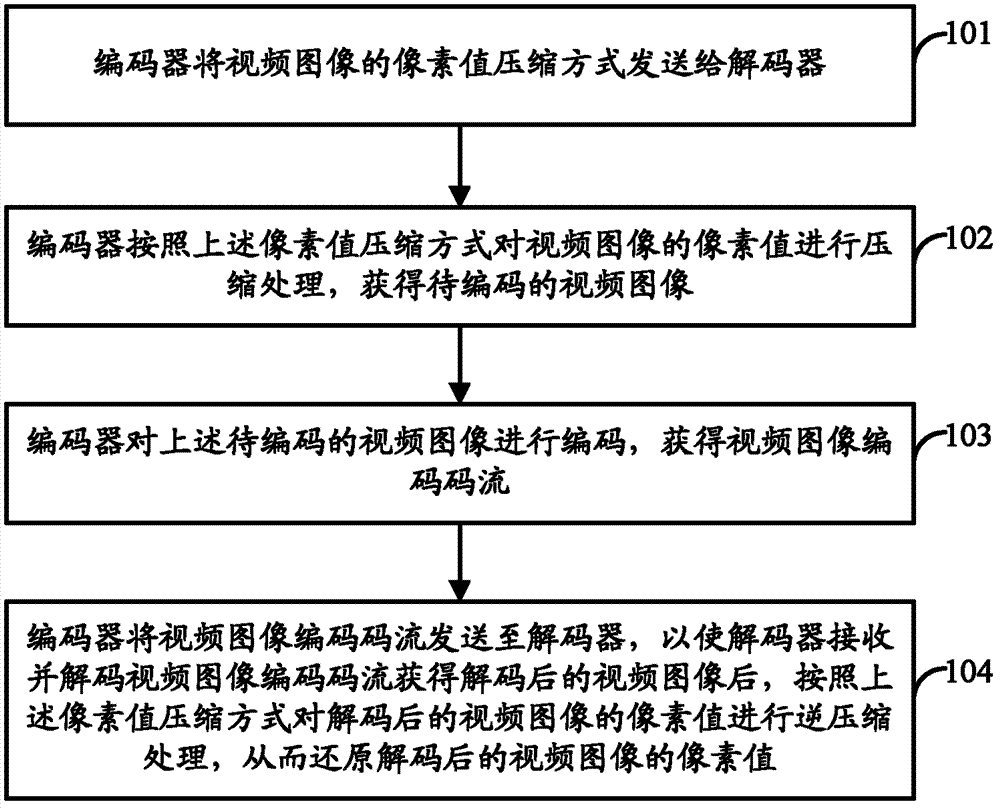
[0041] see figure 1 , figure 1 It is a flowchart of a video processing method provided by an embodiment of the present invention. Such as figure 1 As shown, the video processing method may include the following steps:

[0042] 101. The encoder sends the pixel value compression method of the video image to the decoder.

[0043]In the embodiment of the present invention, the pixel value compression method of the video image may include a mapping relationship between the pixel value of the video image before compression and the pixel value of the video image after compression. The pixel value compression method of the video image involved in the embodiment of the present invention will be described in detail later through specific embodiments. In the embodiment of the present invention, the pixel value of the video image may be represented by bits of a certain length (such as 11111111), or may be represented by a decimal value (such as 256), which is not limited in the embodi...

Embodiment 2

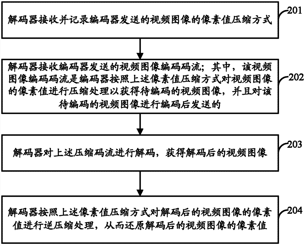
[0060] see figure 2 , figure 2 It is a flowchart of a video processing method provided by an embodiment of the present invention. Corresponding to Embodiment 1 introducing the video processing method provided in the embodiment of the present invention from the perspective of an encoder, Embodiment 2 introduces the video processing method provided in the embodiment of the present invention from the perspective of a decoder. Such as figure 2 As shown, the video processing method may include the following steps:

[0061] 201. The decoder receives and records the pixel value compression method of the video image sent by the encoder.

[0062] In the embodiment of the present invention, the decoder may receive the pixel value compression method of the video image sent by the encoder through the video image transmission channel, network channel, or other dedicated channel, which is not limited in the embodiment of the present invention.

[0063] As described in Embodiment 1 ab...

Embodiment 3

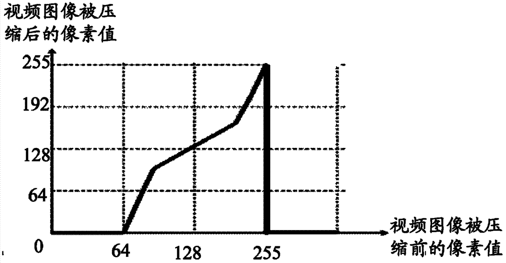
[0072] Embodiment 3 of the present invention illustrates a method for compressing pixel values ​​of video images by way of example.

[0073] As mentioned in the previous embodiments, the pixel value compression method of the video image may include a mapping relationship between the pixel value of the video image before compression and the pixel value of the video image after compression. However, in practical applications, the pixel values ​​of general video images are represented by 8 bits, that is, the value range is 0-255. Therefore, the encoder can shift bits to the right or divide to establish a mapping relationship between the pixel value of the video image before compression and the pixel value of the video image after compression. Specifically, the encoder can shift the pixel value of the video image before compression to the right by at least one bit to obtain the pixel value of the video image before compression, or the encoder can multiply the pixel value of the vi...


PUM


Abstract

Provided are a video processing method and a system and associated equipment. The video processing method comprises that an encoder sends a pixel value compress mode of a video image to a decoder, wherein the pixel value compress mode comprises a mapping relation of the pixel value of the video image before compression and the pixel value of the video image after the compression; the encoder carries out compression processing on the pixel value of the video image according to the pixel value compress mode so as to obtain a to-be-encoded video image; the encoder encodes the to-be-encoded video image so as to obtain encoding code stream of the video image; the encoder sends the encoding code stream of the video image to the decoder so that the decoder receives and decodes the encoding code stream of the video image so as to obtain the video image after decoding, inverse compression processing is carried out on the pixel value of the video image after the decoding according to the pixel value compress mode, and therefore the pixel value of the video image after decoding can be restored. The embodiment of the video processing method and the system and the associated equipment can improve video image compression quality under low transmission channel bandwidth.

Description

technical field [0001] The present invention relates to the technical field of video processing, in particular to a video processing method and system, and related equipment. Background technique [0002] In video communication applications, the compression degree of video images is closely related to the transmission channel bandwidth of video images, that is, after the video images are encoded by the encoder, the bit rate of the compressed code stream obtained cannot exceed the transmission channel bandwidth, otherwise it will There may be a possibility of code stream data loss, resulting in poor video image quality decoded by the decoder. Therefore, the encoder usually uses a certain encoding method to encode the video image, so as to ensure that the bit rate of the obtained compressed bit stream does not exceed the bandwidth of the transmission channel. [0003] H.264 is a video codec standard formulated by the Telecommunication Standardization Department of the Interna...

Claims


Application Information

Patent Timeline
IPC IPC(8): H04N7/26
CPCH04N7/26H04N19/00078H04N19/00H04N19/61H04N19/12H04N19/85H04N19/51
Inventor 王浦林覃永宁
Owner HUAWEI TECH CO LTD
Learn More