
Food processor locking mechanism

A technology of food processor and locking mechanism, which is applied in home appliances, applications, kitchen utensils, etc. It can solve problems such as inconvenient access, accidental injury, food overflow and waste, etc., so that it is very easy to promote and use, avoid misuse, cost saving effect

Active Publication Date: 2013-05-15
ELEC TECH ZHUHAI CO LTD
View PDF6 Cites 19 Cited by
  • Summary
  • Abstract
  • Description
  • Claims
  • Application Information

AI Technical Summary

Problems solved by technology

Moreover, they must be designed to rotate clockwise to conform to people's daily behavior norms, otherwise it will cause misoperation and lead to safety hazards or the opposite result.
[0005] But because the cup holder is located at the bottom of the cup body assembly, it is inconvenient to take, so people usually also have a handle for taking the cup body assembly conveniently on the cup body
When attaching or removing the cup assembly from the base, people tend to exert force on the easy-to-grasp cup instead of the cup holder, and when attaching the cup assembly to the base, due to They are all rotated clockwise. The installed cup body and cup holder will not become loose due to the clockwise rotation of the cup holder and base. However, when the cup assembly is removed from the base counterclockwise, due to the well-known The reason is that it is very likely to cause the failure of the connection of the cup body assembly, so that the cup body is separated from the cup holder before the base and becomes loose, but the cup holder and the base do not separate. Once the cup is filled with food, it will not only cause Food spills cause waste, especially if the cup is heated food, it will cause accidental injury
Therefore, it causes great inconvenience to users

Method used


Image

  • Food processor locking mechanism
  • Food processor locking mechanism
  • Food processor locking mechanism

Examples


Embodiment Construction

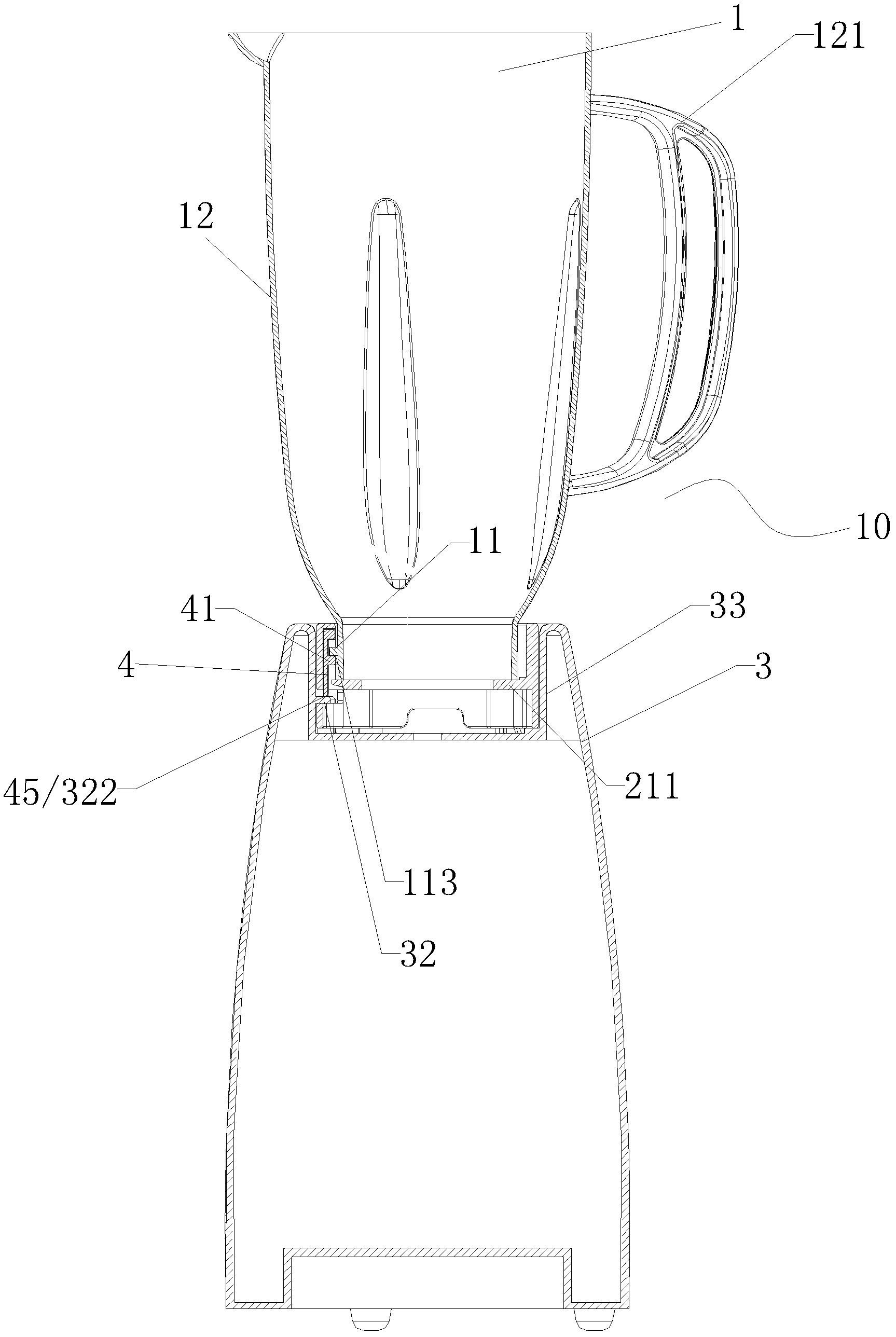
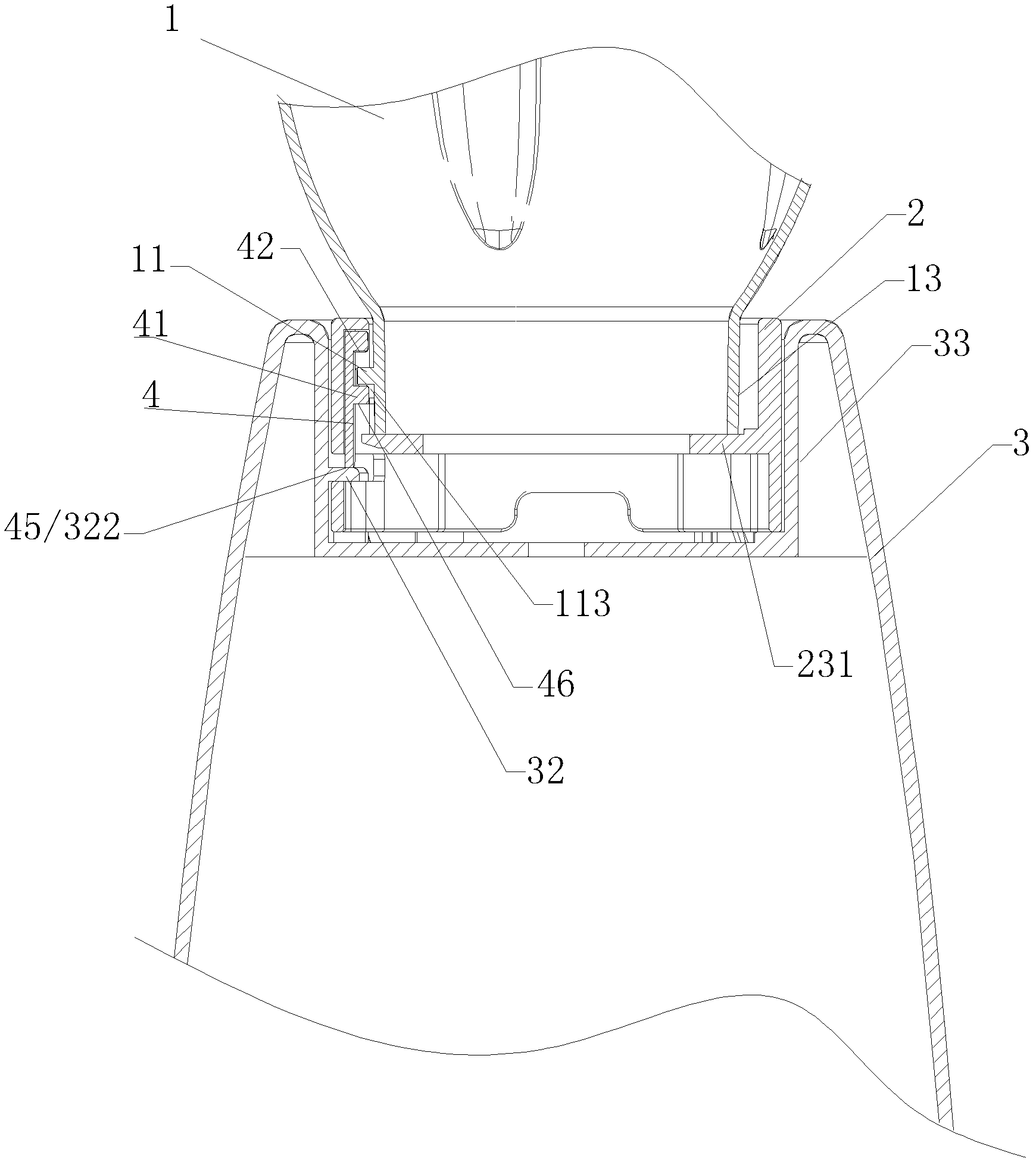
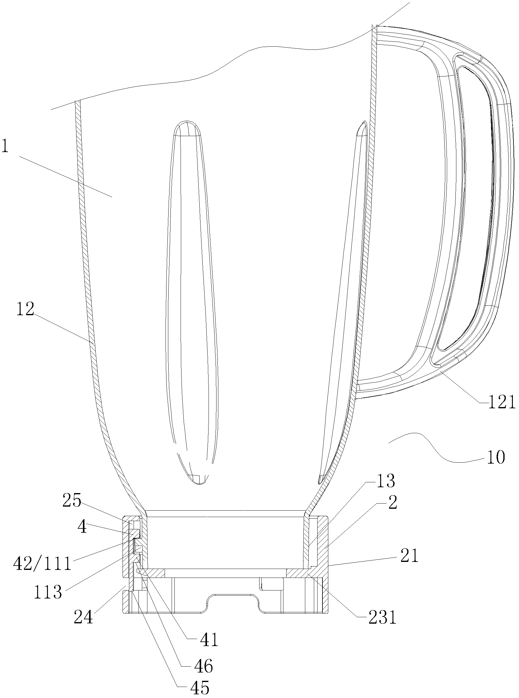
[0022] The invention discloses a locking mechanism of a food processor, please refer to Figure 1 to Figure 8 As shown, it includes a first structural member 1, a second structural member 3 and a connecting member 2, and the connecting member 2 is screwed with the first structural member 1 and the second structural member 3 in a convenient and separable manner. connection; the first structural member 1 and the connecting member 2 are composed into a first structural assembly 10; wherein: it also includes at least one locking block 4 installed on the connecting member 2, and the locking block 4 includes three Two working positions: initial position, first position and second position; when the connecting member 2 is separated from the first structural member 1 and the second structural member 3, the locking block 4 is in the initial position and locked The block 4 is supported and connected by the support structure of the connector 2; when the first structural member 1 and the ...


PUM


Abstract

The invention provides a food processor locking mechanism which has the anti-loose function, guarantees reliable connection between components and prevents components from loosing. The food processor locking mechanism comprises a first structure part, a second structure part and a connection part, wherein the connection part is respectively in screw connection with the first structure part and the second structure part in a mode convenient to separate, and the first structure part and the connection part can form a first structure assembly. The food processor locking mechanism further comprises a locking block installed on the connection part, wherein the locking block comprises three work positions of an initial position, a first position and a second position. When the connection part is separated from the first structure part and the second structure part, the locking block is arranged at the initial position. When the first structure part and the connection part are in a screw connection state, the locking block leaves a support structure of the connection part to move to the first position to be matched with and fixedly connected with a location structure of the first structure part. When the first structure assembly and the second structure part are in a connection state, the locking block is positioned at the second position.

Description

technical field [0001] The invention belongs to the technical field of kitchen food processor structures, and in particular relates to a locking mechanism of a food processor with an anti-loosening function. Background technique [0002] It is known that the existing kitchen processors are generally composed of a cup assembly with a cutting assembly on the upper part and a base with a driving mechanism on the lower part, which are connected by a clutch device. In order to make the driving mechanism stable To transmit energy to the cutting assembly, the clutch device must be connected reliably; therefore, the general practice is to use thicker glass as the cup body, and rely on its gravity to firmly support the upper cup body assembly on the lower base assembly. Meet the transmission requirements. And applying the heavy glass cup body to all styles must cause great waste in the economy, and does not meet the needs of modern people. [0003] With the continuous improvement o...

Claims


Application Information

Patent Timeline
IPC IPC(8): A47J43/07
Inventor 王冬雷
Owner ELEC TECH ZHUHAI CO LTD
Learn More