Positioning mechanism for die and pouching die

A technology of positioning mechanism and stamping die, applied in the direction of positioning device, forming tool, manufacturing tool, etc., can solve the problem that the plate flow is not carried out according to the ideal state, the part forming cannot reach the expected state, and the production efficiency of the mold is reduced, etc., to achieve The effect of reducing the difficulty of debugging, improving production efficiency and reliable positioning

Active Publication Date: 2013-05-15
BEIQI FOTON MOTOR CO LTD
View PDF6 Cites 9 Cited by
  • Summary
  • Abstract
  • Description
  • Claims
  • Application Information

AI Technical Summary

Problems solved by technology

In the existing stamping dies, a vertical positioning plate is usually used to guide and position the sheet. In this positioning method, the sheet is particularly prone to inclination, resulting in the flow of the sheet not being carried out in an ideal state during forming. unexpected state
In order to ensure stable positioning, the fitter needs to repeatedly polish the positioning surface of the positioning plate and repeatedly adjust the position of the positioning plate, which increases the difficulty of mold debugging and reduces the production efficiency of the mold

Method used


Image

  • Positioning mechanism for die and pouching die
  • Positioning mechanism for die and pouching die
  • Positioning mechanism for die and pouching die

Examples


Embodiment Construction

[0023] Specific embodiments of the present invention will be described in detail below in conjunction with the accompanying drawings. It should be understood that the specific embodiments described here are only used to illustrate and explain the present invention, and are not intended to limit the present invention.

[0024] In the present invention, unless stated to the contrary, the used orientation words such as "upper and lower" are defined under the working conditions of the positioning mechanism for the mold and the stamping die provided by the present invention.

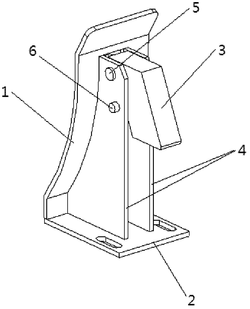
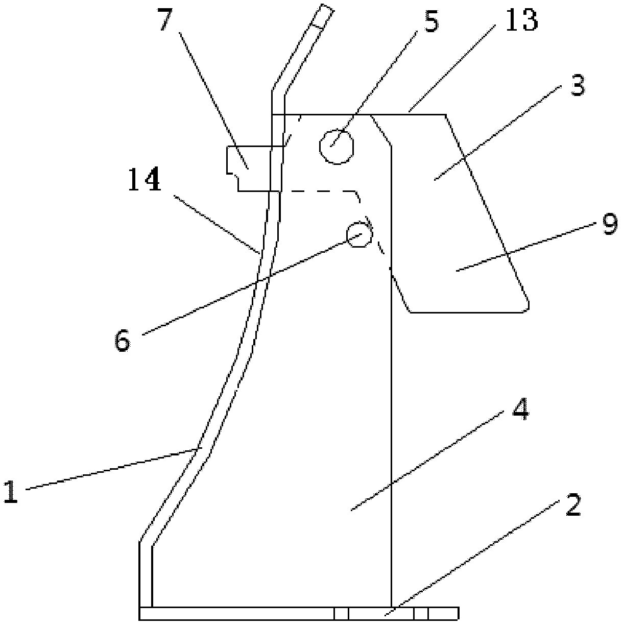
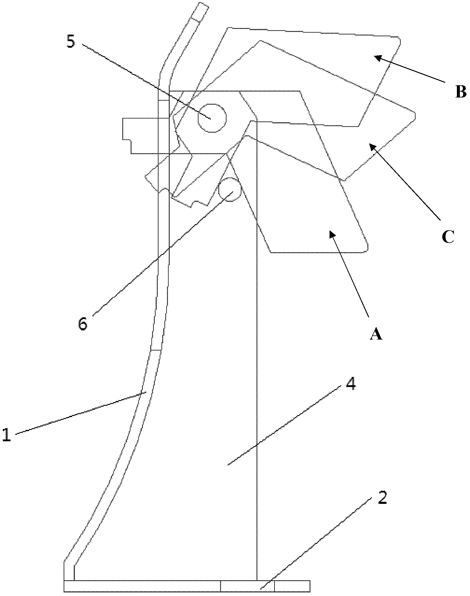
[0025] Such as Figure 1 to Figure 3 As shown, the present invention provides a positioning mechanism for moulds. The positioning mechanism includes a material blocking plate 1, a mounting frame and a material support block 3. The material blocking plate 1 is fixedly connected with the mounting frame, and the blocking plate The material plate 1 is provided with an opening, the material support block 3 has a ...


PUM


Abstract

The invention provides a positioning mechanism for a die. The positioning mechanism for the die comprises a stuff-stopping plate (1), an installation rack and a stuff-supporting block (3). The stuff-stopping plate is fixedly connected with the installation rack. An opening is formed in the stuff-stopping plate. The stuff-supporting block is provided with a stuff-supporting part (7). The stuff-supporting block is installed on the installation rack in a pivoting mode. The stuff-supporting block is provided with a first working position and a second working position, wherein when the stuff-supporting block is located at the first working position, the stuff-supporting part of the stuff-supporting block stretches out of the opening of the stuff-stopping plate, the upper surface (13) of the stuff-supporting part (7) is in a horizontal state, and when the stuff-supporting block is located at the second working position, the stuff-supporting part of the stuff-supporting block retracts back from the opening of the stuff-stopping plate. Furthermore, the invention further provides a punching die which includes the positioning mechanism. Due to the positioning mechanism, sheet materials can be stably positioned without fitters repeatedly grinding and debugging, debugging difficulty of the die is reduced, and production efficiency of the die is improved.

Description

technical field [0001] The invention relates to a positioning mechanism for a mold and a stamping die including the positioning mechanism. Background technique [0002] In the field of stamping dies, whether the positioning of the plate is stable or not directly affects the forming effect of the part. In the existing stamping dies, a vertical positioning plate is usually used to guide and position the sheet. In this positioning method, the sheet is particularly prone to inclination, resulting in the flow of the sheet not being carried out in an ideal state during forming. Not in the expected state. In order to ensure stable positioning, the fitter needs to repeatedly polish the positioning surface of the positioning plate and repeatedly adjust the position of the positioning plate, thereby increasing the difficulty of mold debugging and reducing the production efficiency of the mold. Contents of the invention [0003] The present invention aims to overcome the above prob...

Claims


Application Information

Patent Timeline
Patent Type & Authority Applications(China)
IPC IPC(8): B21D43/00B21D37/10
Inventor 张杰
Owner BEIQI FOTON MOTOR CO LTD
Why Eureka
Try Eureka