Cantilever grinding machining method for vane using three-axis linkage interpolation

A three-axis linkage and grinding technology, which is applied in the direction of grinding workpiece supports, metal processing equipment, grinding/polishing equipment, etc., can solve the problems of blade clamping deformation, low machining accuracy and efficiency, and high cost of machine tools. Achieve the effects of reducing processing vibration and stress deformation, avoiding clamping deformation, and reducing adverse factors

Inactive Publication Date: 2013-05-15
BEIHANG UNIV
View PDF6 Cites 14 Cited by
  • Summary
  • Abstract
  • Description
  • Claims
  • Application Information

AI Technical Summary

Problems solved by technology

[0004] Since the interpolation accuracy, dynamic rigidity and motion speed of CNC machine tools will decrease correspondingly with the increase of the number of linkage axes, therefore, in the process of machining blades, the more axes of CNC machine tools involved in linkage, the higher the machining accuracy and processing efficiency will be. Low, at the same time, the cost of machine tools is also high
The double-end fixed installation of the blade or the auxiliary support on the blade surface are a kind of clamping over-positioning, which will generate corresponding clamping internal stress in the blade, resulting in clamping deformation of the blade. The clamping stress is released, and the clamping deformation of the blade is restored, so that the blade loses the machining accuracy and seriously affects the machining geometric accuracy of the blade

Method used


Image

  • Cantilever grinding machining method for vane using three-axis linkage interpolation
  • Cantilever grinding machining method for vane using three-axis linkage interpolation
  • Cantilever grinding machining method for vane using three-axis linkage interpolation

Examples


Embodiment Construction

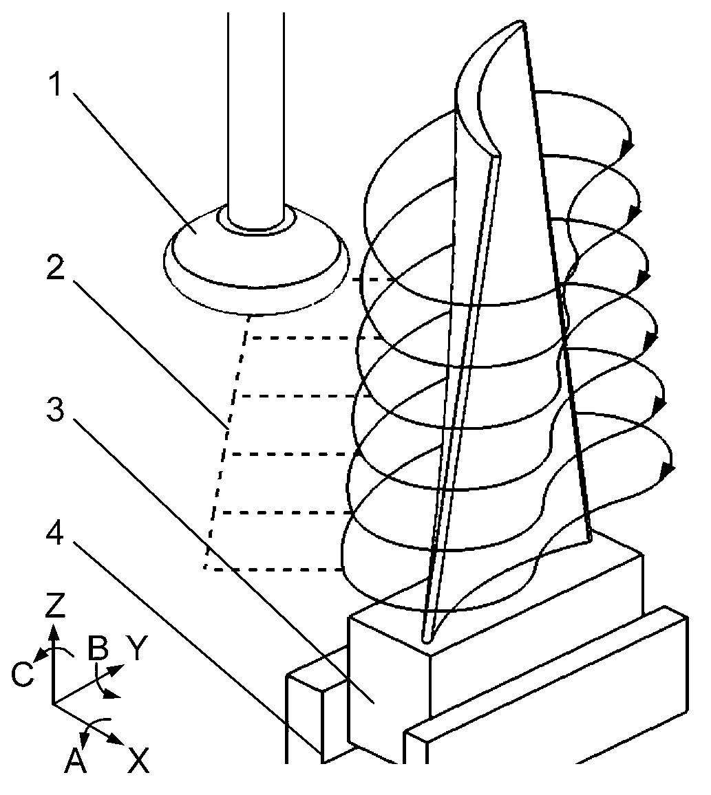
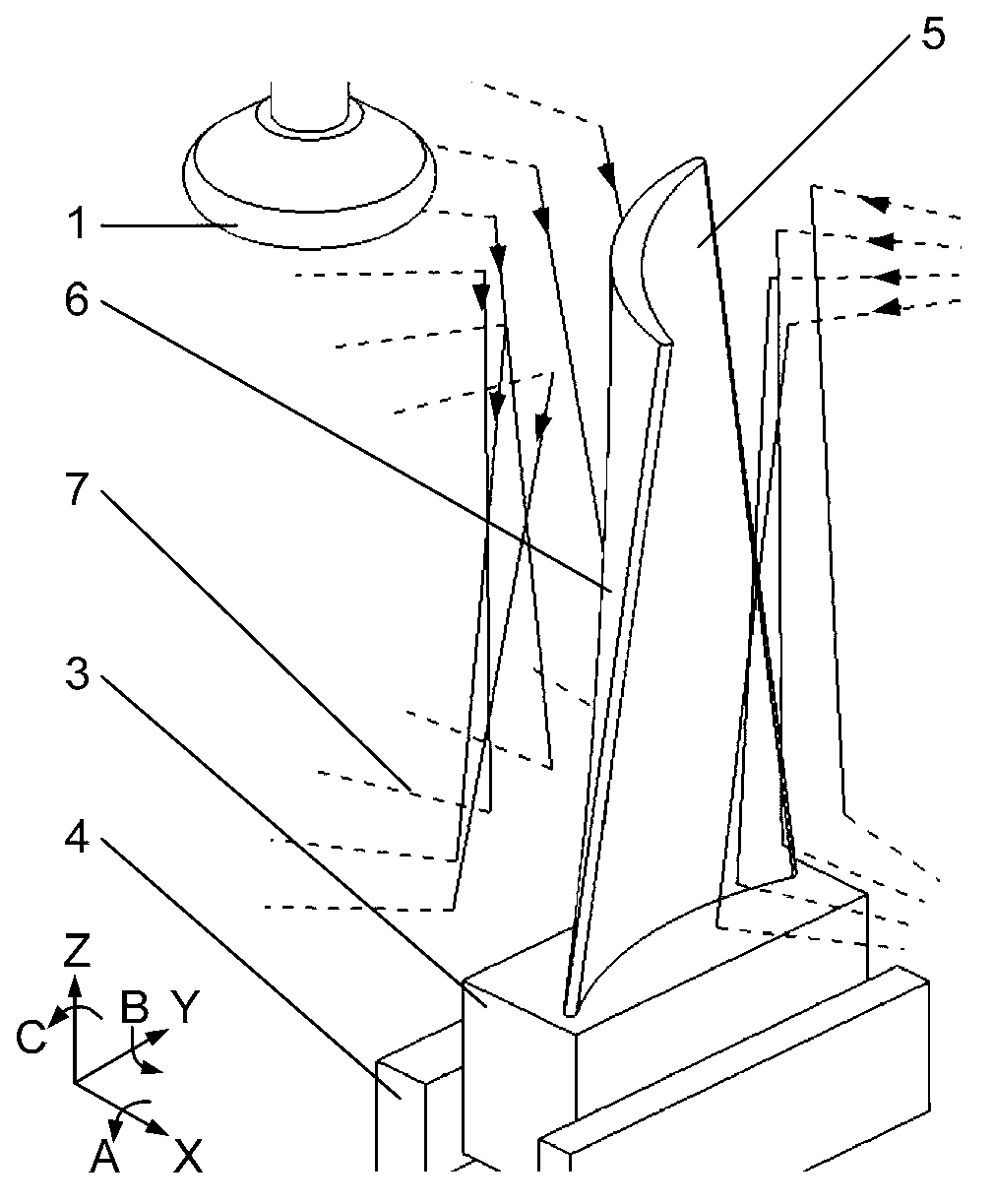
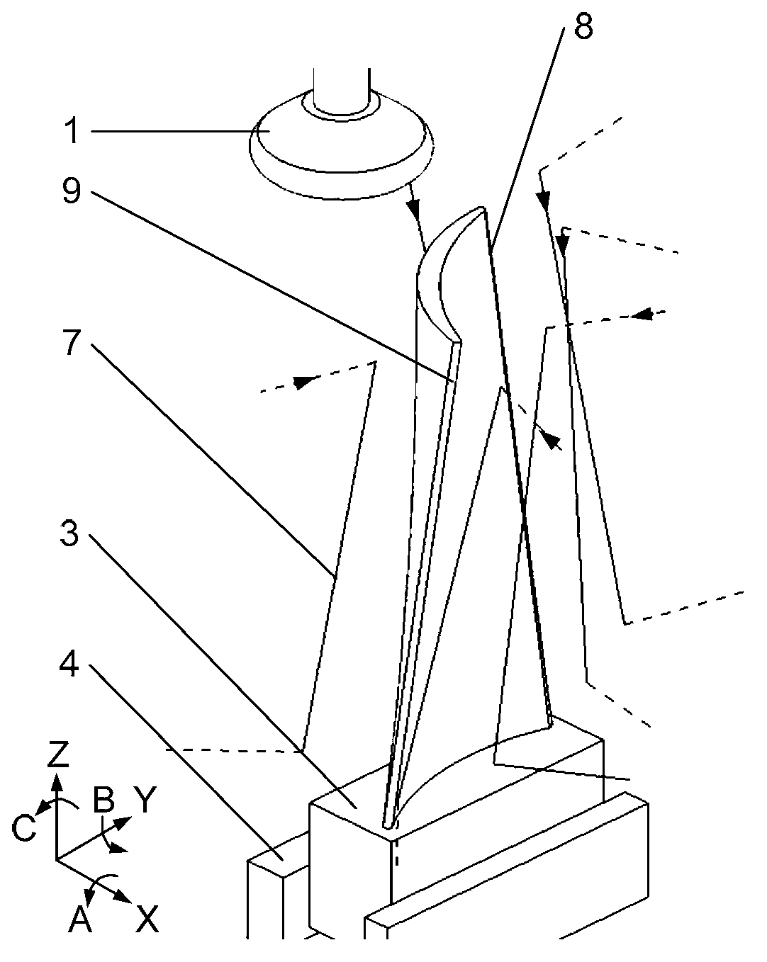
[0021] The invention utilizes the three-axis linkage interpolation motion of the numerical control machine tool, the single-end cantilever of the blade is clamped on the numerical control machine tool, and the profile surface of the blade is ground by a grinding wheel. According to the position of the blade relative to the machine tool after single-end clamping and the structure type of the CNC machine tool, different three axes can be selected for interpolation motion, so as to obtain the grinding motion track of the grinding wheel. The present invention will be further described in detail through specific embodiments below in conjunction with the accompanying drawings.

[0022] See Figure 4 , the present invention uses a three-axis linkage interpolation blade cantilever grinding method, the specific steps of the method are as follows:

[0023] Step 1: Determine the grinding method of the blade surface according to the structure type, motion mode and blade structure of the ...


PUM


Abstract

A cantilever grinding machining method for a vane using three-axis linkage interpolation comprises four steps: (1) ascertaining the grinding method of a vane-shaped face according to the structure type and the motion mode of a machine tool and the structure form of the vane; (2) clamping a tenon or a installation reference block of the vane through a single end of a fixture to enable the vane to be firmly fixed on an operating platform of the machine tool and keeping the vane-shaped face portion needing machining in a cantilever state on the numerical control machine tool; (3) selecting three machine tool motion axes suitable for the grinding machining of the vane-shaped face and a grinding wheel to composite a digital control program, and driving the three linear motion axes X, Y and Z, or the axis X, the axis Z and axis C, or the axis Y, the axis Z and the axis C to conduct the three-axis linkage interpolation motion by the digital control program to form a motion trail of the grinding wheel when the vane is in a grinding machining; and (4) enabling the grinding wheel to rotate at a high speed under the driving of a main shaft of the machine tool and move along the motion trail of the three-axis linkage interpolation of the machine tool to achieve the three-axis linkage interpolation cantilever grinding machining of the vane-shaped face.

Description

technical field [0001] The invention relates to a blade surface grinding method, in particular to a blade cantilever grinding method using three-axis linkage interpolation, and belongs to the technical field of blade processing. Background technique [0002] At present, blades with complex profiles are generally milled or polished using four-axis linkage, five-axis linkage or more axis linkage. Support on the surface. [0003] Above-mentioned processing method has following shortcoming at least: [0004] Since the interpolation accuracy, dynamic rigidity and motion speed of CNC machine tools will decrease correspondingly with the increase of the number of linkage axes, therefore, in the process of machining blades, the more axes of CNC machine tools involved in linkage, the higher the machining accuracy and efficiency will be. Low, at the same time, the cost of machine tools is also high. The double-end fixed installation of the blade or the auxiliary support on the blade...

Claims


Application Information

Patent Timeline
Patent Type & Authority Applications(China)
IPC IPC(8): B24B19/14B24B41/06
Inventor 李勋孟凡军陈志同
Owner BEIHANG UNIV
Why Eureka
Try Eureka